
Reference method for measuring releases of particulate from stationary sources: method A
Method A: Determination of Sampling Site and Traverse Points
1.1 Applicability
This method is applicable to flowing gas streams in stacks or ducts. The method is not applicable as written when one or more of the following conditions exist:
- cyclonic flow (see Section 1.6 for confirmation of cyclonic flow);
- reverse flow (see Section 1.6 for confirmation of reverse flow);
- stack or duct diameters less than 0.30 m (1.0 ft);
- non-circular or non-rectangular stacks or ducts; and
- sampling site less than two stack or duct diameters downstream from a flow disturbance, or less than 0.5 stack or duct diameter upstream from a flow disturbance.
1.2 Principle
A sampling site and the number and location of traverse or sampling points are determined to optimize the extraction of a representative sample.
1.3 Location of Sampling Site
Select a site in a straight section of stack or duct located at least eight stack or duct diameters downstream and two stack or duct diameters upstream of any flow disturbance such as a bend, expansion, contraction, visible flame, junction, or stack exit. In the case of rectangular stacks or ducts, an equivalent diameter (De) shall be used in determining the downstream and upstream distances.
where: L represents length, and W represents width.

In circular stacks or ducts, at least two sampling ports with a 90° separation are required. For particulate traverses, one diameter should be in the plane of an upstream flow disturbance.
For rectangular flow areas, ports are located on the most accessible face of the duct or flue. The number of ports will be determined by the total number of traverse points.
1.4 Determination of Traverse Points
When the sampling site is located at least eight diameters downstream and two diameters upstream from a flow disturbance, the required minimum number of traverse points for a circular or rectangular cross section is determined from Table A-1.
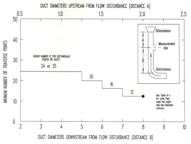
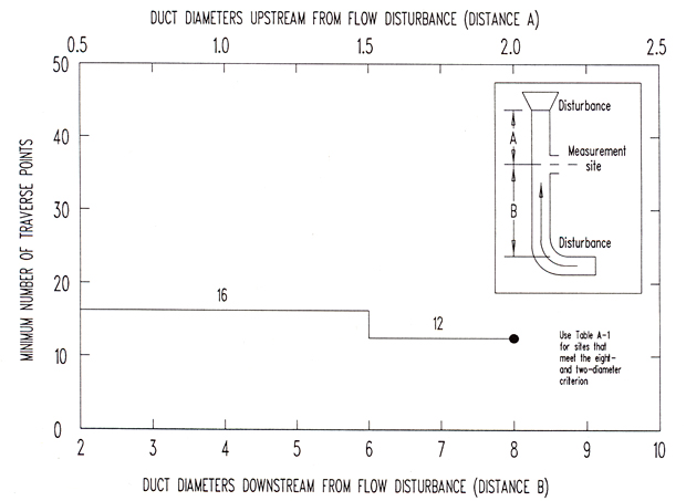
When the eight- and two-diameter criteria cannot be satisfied, the minimum number of traverse points is determined either from Figure A-1 for particulate sampling or from Figure A-2 for velocity measurement. Determine the number of diameters upstream and downstream from the sampling site to the flow disturbances. Then using either Figure A-1 or Figure A-2, determine the minimum number of traverse points corresponding to: (a) the number of duct diameters upstream, and (b) the number of duct diameters downstream. Select the higher of the minimum numbers of traverse points from (a) and (b). In the case of circular cross sections, if the required number of points does not equal a multiple of four then the required number of points must be increased to the next greater multiple of four.
Figure A-1: Minimum Number of Traverse Points for Particulate Sampling
Click to enlarge

Figure A-2: Minimum Number of Traverse Points for Velocity Measurement
Click to enlarge

| Stack or Duct Diameter (m) | Circular Duct | Rectangular Duct |
|---|---|---|
| > 0.61 |
12
|
12
|
| 0.30 to 0.61 |
8
|
9
|
1.5 Location of Traverse Points
For stacks or ducts with a circular cross section, locate the traverse points (as determined from Section 1.4) on two perpendicular diameters according to Table A-2. These points are located at the centroid of equal areas of the cross section.
The minimum distance between the stack wall and a traverse point shall be:
- 2.5 cm (1.0 in) for stacks with diameters greater than 0.61 m (24 in); and
- 1.3 cm (0.5 in) for stacks with diameters less than 0.61 m (24 in).
For rectangular cross sections, the area is divided into as many equal rectangular sections as there are sampling points (determined from Section 1.4). Locate the traverse points at the centroid of these rectangular sections. An example of the location of traverse points for a circular and rectangular stack is illustrated in Figure A-3.
Figure A-3: Location of Traverse Points on Circular and Rectangular
Cross Sections Divided into Twelve Equal Areas

The cross-sectional layout of a rectangular duct shall be chosen such that the ratio of the length to the width is between 1.0 and 2.0.
| Traverse Point Number on a Diameter | 2 | 4 | 6 | 8 | 10 | 12 | 14 | 16 | 18 | 20 | 22 | 24 |
|---|---|---|---|---|---|---|---|---|---|---|---|---|
| 1 | 14.6 | 6.7 | 4.4 | 3.3 | 2.5 | 2.1 | 1.8 | 1.6 | 1.4 | 1.3 | 1.1 | 1.1 |
| 2 | 85.4 | 25.0 | 14.7 | 10.5 | 8.2 | 6.7 | 5.7 | 4.9 | 4.4 | 3.9 | 3.5 | 3.2 |
| 3 | 75.0 | 29.5 | 19.4 | 14.6 | 11.8 | 9.9 | 8.5 | 7.5 | 6.7 | 6.0 | 5.5 | |
| 4 | 93.3 | 70.5 | 32.3 | 22.6 | 17.7 | 14.6 | 12.5 | 10.9 | 9.7 | 8.7 | 7.9 | |
| 5 | 85.3 | 67.7 | 34.2 | 25.0 | 20.1 | 16.9 | 14.6 | 12.9 | 11.6 | 10.5 | ||
| 6 | 95.6 | 80.6 | 65.8 | 35.5 | 26.9 | 22.0 | 18.8 | 16.5 | 14.6 | 13.2 | ||
| 7 | 89.5 | 77.4 | 64.5 | 36.6 | 28.3 | 23.6 | 20.4 | 18.0 | 16.1 | |||
| 8 | 96.7 | 85.4 | 75.0 | 63.4 | 37.5 | 29.6 | 25.0 | 21.8 | 19.4 | |||
| 9 | 91.8 | 75.0 | 63.4 | 37.5 | 29.6 | 25.0 | 21.8 | 19.4 | ||||
| 10 | 97.5 | 88.2 | 79.9 | 71.7 | 61.8 | 38.8 | 31.5 | 27.2 | ||||
| 11 | 93.3 | 85.4 | 78.0 | 70.4 | 61.2 | 39.3 | 32.3 | |||||
| 12 | 97.9 | 90.1 | 83.1 | 76.4 | 69.4 | 60.7 | 39.8 | |||||
| 13 | 94.3 | 87.5 | 81.2 | 75.0 | 68.5 | 60.2 | ||||||
| 14 | 98.2 | 91.5 | 85.4 | 79.6 | 73.9 | 67.7 | ||||||
| 15 | 95.1 | 89.1 | 83.5 | 78.2 | 72.8 | |||||||
| 16 | 98.4 | 92.5 | 87.1 | 82.0 | 77.0 | |||||||
| 17 | 95.6 | 90.3 | 85.4 | 80.6 | ||||||||
| 18 | 98.6 | 93.3 | 88.4 | 83.9 | ||||||||
| 19 | 96.1 | 91.3 | 86.8 | |||||||||
| 20 | 98.7 | 94.0 | 89.5 | |||||||||
| 21 | 96.5 | 92.1 | ||||||||||
| 22 | 98.9 | 94.5 | ||||||||||
| 23 | 96.8 | |||||||||||
| 24 | 98.9 |
1.6 Confirmation of Cyclonic and Reverse Flow
1.6.1 Cyclonic Flow
The presence of cyclonic flow must be determined: (a) at a sampling site located after devices such as in-line turbine fans, cyclones, inertial demisters following venturi scrubbers; and (b) in stacks or ducts having tangential inlets or configurations which induce swirling flow. Cyclonic flow is verified by using the S-type pitot tube and manometer described in Method B and by following these procedures:
- level and zero the manometer;
- position an S-type pitot tube at a traverse point such that the face-opening planes are parallel to the longitudinal axis (zero reference position) of the stack or duct;
- rotate the pitot (up to ± 90°) about its longitudinal axis until the manometer Δp is zero; repeat this procedure for all traverse points; record all angles to the nearest degree; if the pitot does not have to be rotated to produce a null reading then an angle of 0° is recorded for that point; and
- calculate the arithmetic average for the absolute values of all the rotational angles; cyclonic flow is confirmed when the average rotational angle is greater than 15°.
1.6.2 Reverse Flow
The presence of reverse flow must be determined when an obstruction such as baffle plates is located inside the stack or duct, upstream of the sampling site. Reverse flow is confirmed when a negative velocity pressure is measured at one or more sampling points.