
Reference method for measuring releases of particulate from stationary sources: method F
Method F: Calibration Procedure for S-Type Pitot Tube, Dry Gas Meter and Orifice Meter
6.1 Calibration of S-Type Pitot Tube
6.1.1 Principle
The S-type pitot tube and/or probe assembly are calibrated in a wind tunnel against a standard pitot tube having a known coefficient. This pitot tube must be used in the same configuration as it is calibrated. Once calibrated, it is not necessary to calibrate an S-type pitot tube before every field use, except in the following cases:
- when it is to be used in compliance testing;
- when stubborn accretions of particulate matter have affected the area of the impact openings; and
- when the tube has sustained damage or undergone modifications.
In all cases, calibration data shall be recorded, dated, and signed by the party responsible for the calibration. For compliance testing, all calibration data must be submitted to Environment Canada for review and approval prior to testing.
6.1.2 Apparatus
The following items are required:
- Standard pitot tube
-
A standard pitot tube to calibrate the S-type pitot tube. The standard pitot tube shall have a known coefficient in the range 0.98 to 1.0. The impact and static hole openings should be free of dirt. It is recommended that standard pitot tubes used for calibrating other pitot tubes should not be used in dirty gas streams.
- S-type pitot tube
-
Also known as the Stausscheibe or reverse type pitot tube. The S-type pitot tube may be used alone, attached to a temperature sensor, or mounted on a probe.
- Differential pressure indicators
-
Two differential pressure devices such as inclined manometers to measure the velocity pressures to within 0.1 mm (0.005 in) H
2O on the 0 to 25 mm (0 to 1.0 in) H
2O range and 1 mm (0.05 in) H
2O on the 25 to 250 mm (1 to 10 in) H
2O range. Equivalent differential pressure devices such as micromanometers may be used provided that they are calibrated against a primary pressure standard before use.
- Wind tunnel
- A flowing gas stream confined in a duct with a constant cross section that is either circular or rectangular. The minimum cross-sectional area must be 5600 cm 2 (864 in 2). The flow system must be capable of producing variable velocities [from 3 m/s to at least 20 m/s (10 to 60 ft/s)]. This generated velocity must have no temporal variations to ensure steady flow during calibration. The test site must be situated at least eight diameters downstream and two diameters upstream from a flow disturbance. Deviations from the eight- and two-diameter criteria are acceptable provided that it can be demonstrated that the flow is stable and parallel to the longitudinal axis of the duct. The test section of the wind tunnel shall contain two test ports, one each for the standard and S-type pitot tubes. It is recommended that the working section be constructed of a transparent material to facilitate the positioning and alignment of the probe assembly and pitot tubes.
6.1.3 Procedure
Locate the two calibration points. The two points should be near the centre of the tunnel separated by at least two tunnel diameters distance. Before the S-type pitot tube (mounted or unmounted) is calibrated, measure the velocity pressures (Δp) at each point to ensure that the velocities are the same. This may be done by measuring Δp with two standard pitot tubes simultaneously or by alternately measuring the Δp at each site with a single standard pitot tube. Position the standard pitot tube (reference) with known coefficient near the centre of the wind tunnel and position the S-type pitot tube a minimum of two tunnel diameters downstream of the reference. Ensure that both pitots are facing directly into the gas stream and that both ports are completely sealed. Connect the manometers to the pitot tubes and ensure that they are filled with the fluid of proper density. Inspect and leak check all pitot lines and level and zero the manometers.
Record the ambient temperature and barometric pressure. Turn on the wind tunnel fan and allow the flow to stabilize. Read the velocity pressure heads from the standard pitot tube (Δp)std and the S-type pitot tube Δp and record these values in Figure F-1. At least five velocities must be generated that cover the expected velocity range in the field.
Figure F-1: Pitot Tube Calibration Data Sheet

In the case of single S-type pitot tubes with and without a mounted thermocouple, both legs of the pitot tube must be identified e.g., "A" and "B". It is not necessary to calibrate with both legs facing the flowing stream; however, the pitot tube must be used in the field in the same way it was calibrated in the flowing gas stream. In the case of a probe assembly (pitot tube, thermocouple, and nozzle), it is recommended that the probe assembly be calibrated with the anticipated nozzle to be used in the field.
The wind tunnel must have a sufficiently large cross-sectional area in relation to the projected area of a probe assembly. The projected area (Figure F-2) of the probe must be at most 2% of the duct area to obtain reliable coefficients. When the projected area of the probe exceeds this criterion, the blockage area may be reduced by moving the probe back a few inches or by using a larger wind tunnel.
Figure F-2: Projected Area Models for Typical Probe Assemblies

6.1.4 Calculations
Pitot tube coefficient (Cp)
Calculate the pitot tube coefficient for each wind tunnel setting using Equation F-1. The coefficient for the pitot tube is calculated by averaging the individual coefficients.
Equation F-1
Calculate the absolute differences between the average pitot tube coefficient and the coefficient for each of the wind tunnel settings. The average of these differences must not exceed 0.01.
6.1.5 Nomenclature
- Cp
-
coefficient of the S-type pitot tube (mounted or unmounted)
- (Cp)std
-
coefficient of the standard pitot tube (if unknown use 0.99)
- Δ p
-
velocity pressure measured by the S-type pitot tube, kPa
- (Δ p)std
- velocity pressure measured by the standard pitot tube, kPa
6.2 Calibration of Dry Gas Meter and Orifice Meter
6.2.1 Principle
The dry gas meter and the orifice meter of the particulate sampling train shall be calibrated against a primary standard before each compliance testing sampling survey. The following procedure is based on a wet test meter that was calibrated against a primary standard.
6.2.2 Apparatus
A wet test meter or equivalent device capable of measuring the volume within (plus or minus) 1% accuracy at a rate approximating that of the dry gas meter (e.g., 30 L (1 ft3) per revolution) shall be used.
6.2.3 Procedure
Before calibrating the dry gas and orifice meters, the pressure and vacuum side of the sampling console must be checked for leaks. The following procedure is recommended for leak checking that portion of the train from the pump to the orifice meter (Figure F-3).
Figure F-3: Leak Check of Meter Box

Close the main shut-off valve on the meter box. Attach a flexible tube to the orifice exhaust pipe. Disconnect and vent the low pressure side of the orifice manometer and plug or cap the low side of the orifice tap. Pressurize the system to 13 to 18 cm (5 to 7 in) H20 by blowing into the flexible tubing. Pinch the tubing and observe the manometer reading for one minute. A loss of pressure on the manometer indicates a leak between the pump and orifice meter. Correct the leak before calibration.
The vacuum or suction side of the pump may be checked by the following procedure. Plug the suction (sample) line going into the sampling console and open the coarse control valve. Start the pump and adjust the fine control (by-pass) valve to a vacuum of 380 mm (15 in) Hg. Check the dry gas meter needle for movement. No movement on the dial should be indicated following the initial purge of the line. Any leaks must be corrected before proceeding to the calibration procedure.
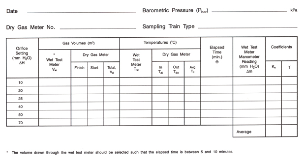
Connect the components as shown in Figure F-4. Level all components, zero all manometers, and inspect and leak check all sample lines. Operate the equipment with the orifice manometer set at 13 mm (0.5 in) H20 for at least 15 minutes to allow he pump to warm up and to permit all interior surfaces of the wet test meter to become wetted. Perform the tests by drawing the desired volume of air through the wet test meter at each of the orifice manometer settings. Record the dry test meter volumes, times, temperatures, and manometer readings in Figure F-5.
Figure F-4: Assembly for Calibration of Dry Gas Meter and Orifice Meter

Figure F-5: Dry Gas Meter and Orifice Meter Calibration Data Sheet
Click to enlarge

6.2.4 Calculation
Dry gas meter correction factor (γ)
Calculate γ, the dry gas meter correction factor for each orifice setting by using Equation F-2.
Equation F-2
where :

If the average value of γ is not within the range 0.95 to 1.05, the dry test meter must be adjusted internally and the calibration procedure repeated. Each value of γ must be within (plus or minus) 1.5% of the average value. If not, the calibration must be repeated.
Orifice meter coefficient (Ko)
The flow through an orifice meter for each orifice setting may be determined by using Equation F-3.
Equation F-3
Alternately, Qm may also be expressed in terms of the flow rate through the wet test meter using Equation F-4.
Equation F-4
The Ko value for the orifice may be obtained by averaging the individual Ko at each orifice setting which are calculated by equating Equation F-3 to Equation F-4 and solving for Ko.
6.2.5 Nomenclature
- Bwo
-
proportion by volume of water vapour (saturated) passing through the wet test meter calculated from partial pressure data published in technical handbooks, dimensionless
- Δ H
-
pressure drop across the orifice meter, kPa
- Ko
-
orifice coefficient (m
3/min) [(kg/kmol)/K]
½
- Δ m
-
wet test meter manometer reading, kPa
- Ms
-
molecular weight of saturated air, kg/kmol
M s = 28.95 ( 1-B wo ) + 18B wo - Pbar
-
barometric pressure, kPa
- Qm
-
flow rate through the orifice meter, m
3/min
- Td
-
average temperature of dry gas meter, K
- Tdi
-
dry gas meter inlet temperature, K
- Tdo
-
dry gas meter outlet temperature, K
- Tw
-
temperature of the wet test meter, K
- Vd
-
actual volume drawn through dry gas meter, m
3
- Vw
-
actual volume drawn through wet test meter, m
3
- γ
-
the dry gas meter correction factor, dimensionless
- θ
- time, min.