
Reference method for measuring emissions of nitrogen oxides from stationary sources: chapter 8
8 Procedure
8.1 Sampling
8.1.1 Preparation of Collection Train. Pipet 25.0 ml of absorbing solution into a calibrated sampling flask and attach the three-way stopcock to the flask (Note 1) with the T-bore in the purge position. Assemble the sampling apparatus as shown in Figure 1, making sure that all ground glass joints have been properly greased and that all joints and fittings are tight and leak-free. Turn the flask stopcock to the evacuate position and evacuate the flask to the incipient boiling point of the solution. If the incipient boiling point of the solution cannot be seen, it will be indicated on the manometer by a low and constant reading (usually around 20-30 mm Hg absolute). Shut off the pump valve and then the pump. Check for leakage by observing the manometer for any pressure increase. If there are leaks in the sampling train, eliminate them by appropriate action.
8.1.2 Sample Collection. Insert the sampling probe about one third to halfway into the stack or duct in such a way as to prevent leakage of air into the stack around the probe. Turn the flask stopcock to the purge position. Using a pump or a valved rubber squeeze-bulb, thoroughly purge the sampling probe and the flask stopcock with the sampling gas until the probe and stopcock are warmed to the gas temperature and free from condensate. If condensation remains, heat the probe and purge until the condensation disappears. With the pump valve and pump shut off, turn the flask stopcock to the evacuate position and record the flask temperature and absolute pressure. A data sheet similar to Figure 2 can be used to record the field data. Immediately turn the stopcock to the sampleposition so that the gas enters the flask and the pressures in the flask and the sample line are equalized (usually about 15 seconds are sufficient). Turn the stopcock to the purge position and remove the flask from the sampling train assembly. Shake the flask for 5 minutes and allow the gas to remain in contact with the absorbing solution overnight.
Note 1 - The end 6 mm of the male T24/40 standard taper joint is not lubricated, to minimize contact of the gas sample with stopcock grease during absorption.
8.2 Sample Recovery
8.2.1 After the absorption period is completed, record the barometric pressure and the room temperature where the sample has stood. Connect one arm of the sample flask stopcock to the open-end manometer, turn the stopcock to open the flask to the manometer, and read the difference between the mercury levels in the manometer. The absolute internal pressure in the flask is then the barometric pressure less this difference.
8.2.2 Transfer the absorbing solution quantitatively from the flask into a 200-ml evaporating dish (Notes 2, note3, note4). Pipet 25.0 ml of unused absorbing solution into another evaporating dish for a blank and add the same amount of water to this dish as was used in transferring the sample. Proceed with the blank in the same manner as directed for the sample.
Note 2 - If the sample is expected to have a high concentration of oxides of nitrogen, transfer It to a 50-ml volumetric flask instead of the evaporating dish, and dilute to the mark with water. Select a suitable aliquot and pipet it into a 200-ml evaporating dish. Likewise, dilute 25.0 ml of unused absorbing solution to 50 ml and pipet an aliquot equal to that of the sample into a 200-ml evaporating dish for a blank.
Note 3 - To save time a 15-ml aliquot of the used absorbing solution may be pipetted into the evaporating dish, rather than quantitatively transferring the whole solution. This is permissible if the concentration of nitrogen dioxide (NO2) is high enough, and if the evacuation of the flask prior to admitting the sample was to the incipient or flash boiling point of the unused absorbing solution. Evacuation up to I minute after flash boiling appears to result in about a 1-percent decrease in the volume of the solution.
Note 4 - If it is necessary to reuse the sampling flask immediately or to ship the used absorbing solution back to a laboratory for analysis, the entire used absorbing solution or a 15-ml aliquot may be quantitatively transferred to a leak-free bottle until ready for analysis.
Figure 2. NOx Data sheet
Description of Figure 2 - Equation
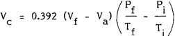
The corrected volume of sample gas, Vc, in millilitres, is equal to 0.392 multiplied by the difference between the volume of sample collection flask, Vf, in millilitres, and the volume of absorbing solution used, Va, in millilitres. The result is then multiplied by the difference between the final and initial pressure to temperature ratio, where the final pressure is the absolute pressure in the flask after absorption period, Pf, in millimetres of mercury, the final temperature is the final absolute temperature of flask after absorption period, Tf in degrees Kelvin, the initial pressure is the initial absolute pressure in flask prior to sampling, in millimetres mercury and the initial temperature is the initial absolute temperature of flask prior to sampling in degrees Kelvin.
|
Sample Number
|
Date and Time
|
Volume of Flask Vf ml |
Volume of Absorbing Solution Va ml |
Initial Absolute Pressure Pf , mm Hg |
Initial Temperature Ti , °K |
Final Absolute Pressure Pf , mm Hg |
Final Temperature Tf , °K |
Corrected Volume Vc ml
|
8.3 Analysis
8.3.1 Add NaOH solution to the sample solution in the evaporating dish and to the blank until each is just basic to litmus or pH paper. Do not add any excess NaOH. Evaporate each to dryness on a water bath and allow to cool. Very carefully add 2 ml of phenol-disulphonic acid solution to each residue and triturate with a polyethylene rod to ensure complete contact of the residue with the solution. Add 1 ml of water and 4 drops of H2SO4 (sp.gr. 1.84) to each and heat on the water bath for 3 minutes with occasional stirring. Allow the mixture to cool, add 10 ml of water to each and mix well by stirring. Add 15 ml of fresh, cool NH4OH dropwise to each with constant stirring. Test with litmus paper to make sure an excess of the NH4OH is present.
8.3.2 If visible particles can be seen in the solutions, filter through 7-cm, rapid, medium-texture filter papers (Note 5) into 50-ml volumetric flasks. Wash the evaporating dishes three times with 4 to 5 ml of water and pass the washings through the filters. Make up the volumes of the solutions to 50 ml with water and mix thoroughly.
Note 5 - The use of the same grade of filter paper should be adhered to in preparing the calibration curves and running the samples. It has been found that some yellow colour is retained on the paper when filtering more concentrated samples. This factor must be taken into account by using the same type of filter paper throughout, or by continuing to wash until no colour is retained in any case. Alternatively, the ammoniacal solutions may be centrifuged, instead of filtered, after dilution to 50 ml.
8.3.3 Read the absorbance of the sample solution against the blank in suitable equipment for measurement at 405 nm. If the absorbance falls beyond the range of calibration, thinner cells may be used or a suitable aliquot selected. Dilute the aliquot and the blank to the same volume and read the absorbance of the sample aliquot against that of the blank aliquot.
8.3.4 Convert the photometric readings to micrograms of NO2 by means of the calibration curves.
Note 6 - The calibration curves must not be assumed to be usable over any protracted length of time. It is suggested that standards be run along with the samples each time a set is run, or at least every few days if samples are being run daily.