
Standard reference methods for source testing: measurement of asbestos emissions from mining and milling
List of figures
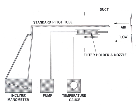
Figure S-3-1: Sampling train schematic
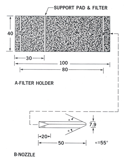
Figure S-3-2: Design specifications of filter holder and nozzle
Figure S-3-3: Schematic for adjusting sampling unit to isokinetic conditions
Figure S-3-4: Data sheet - Drill baghouse sampling
Environmental protection service report series
Reports pertaining to regulations, codes, and protocols describe current legislatron and administrative approaches favoured by the Environmental Protection Service.
Other categories in the EPS series include such groups as Policy and planning; Economic and technical review; Technology development; Surveillance; Briefs and submissions to public inquiries; and Environmental impact and assessment.
Inquiries pertaining to Environmental Protection Service reports should be directed to the Environmental Protection Service, Department of the Environment, Ottawa K1A 0H3, Ontario, Canada.
Method S-3: sampling of drill baghouse exhaust emissions
S-3.1 Scope
Due to the configuration of exhaust ducting from drill baghouses it is not practical to sample these sources for asbestos emissions using Method S-1. Method S-3, though less rigorous, has been developed as a practical alternative which allows an estimation of asbestos emissions from these sources.
S-3.2 Apparatus
Standard pitot tube. This pitot tube is used to determine the velocity pressure in the gas stream. The pitot tube coefficient (Cp) for the unit must be used if known; otherwise the value 0.99 will suffice.
Differential pressure gauge. An inclined manometer, or equivalent, capable of measuring the velocity pressure to within 0.01 in. H2O is required.
Temperature gauge. A thermometer is required which will measure ambient temperatures to within ± 1°C.
Barometer. A barometer capable of measuring absolute atmospheric pressure to within 2.5 mm Hg is required.
Sampling train. See Figure S-3-1.
Nozzle. A metal or plastic nozzle with a sharp tapered leading edge is required. Design specifications are given in Figure S-3-2.
Filter holder. A plastic filter holder, or equivalent, to which the sampling nozzle can be attached is required. It consists of a plenum chamber ahead of the filter, a filter support pad and a small chamber behind the pad. It can be constructed from commercially available filter holders designed for 37 mm filters. Details of construction and design specifications are given in Figure S-3-2.
Filters. A 37 mm, 0.8 μm cellulose ester membrane filter is used. The filter is printed with a grid which divides it into eight 45° axial sectors. Each sector is further divided into an inner and outer annular area with area ratios of 1:3 respectively. (Figure S-3-2.)
Pump. A vacuum pump capable of maintaining an isokinetic sampling rate for a period of up to four hours is required.
Rotameter. A calibrated rotameter accurate to within ± 2% is required for adjustment of the flow rate through the nozzle to isokinetic conditions.
Figure S-3-1: Sampling train schematic
Description of figure S-3-1
Sampling train schematic. Consists of duct, air flow, filter holder and nozzle, standard pitot tube, inclined manometer, pump and temperature gauge.
Figure S-3-2: Design specifications of filter holder and nozzle
Description of figure S-3-2
Design specifications of filter holder and nozzle. Consists of filter holder, nozzle and measurements.
S-3.3 Procedures
S-3.3.1 Selection of sampling site and sampling point
A sampling site in the exhaust duct from the drill baghouse is chosen to optimize the extraction of a representative sample. Select a section of ducting, after the fan, from which the clean air from the baghouse is exhausted to atmosphere. The sampling point is located at the centre of the duct cross-section and as far downstream of the fan blades as the duct configuration allows.
S-3.3.2 Measurement of exhaust gas velocity
The exhaust gas velocity is determined from gas density and measurement of exhaust gas velocity pressure using a standard pitot tube.
Insert the pitot tube and temperature measuring device into the exhaust stream at the preselected sampling point.
Ensure that all connections between the pitot tube and inclined manometer are tight and leak free. Measure and record the velocity pressure and temperature at the sampling point. Record the absolute barometric pressure.
The exhaust gas density is assumed to be the same as dry air.
Based on these measurements, the exhaust gas velocity is calculated from Equation S-3-1.
Equation S-3-1
Us = Kp Cp (Δp)1/2 (Ts / PsM)1/2
where
Us = exhaust gas velocity, ft/min
Kp = constant,
5120 (ft/min) (lb-in. Hg / lb-mole °R in. H2O)1/2
Cp = standard pitot tube coefficient
Δp = standard gas velocity pressure, in. H2O
Ts = absolute exhaust gas temperature, °R
M = molecular weight of gas (assume dry air), 29.0 lb/lb-mole
Ps = absolute exhaust gas pressure (assume equal to absolute barometric pressure), in. Hg
S-3.3.3 Preparation of filter unit
Using a pair of clean tweezers place a filter, with the printed side up, on the support pad of the holder. The "T" imprinted on the filter should be aligned with an external marking on the holder to allow proper orientation in the exhaust stream. Replace the upper cover of the holder, insert the plugs and then place a wet cellulose collar around the unit so that it seals the joint between the insert and lower cover of the holder. Allow the collar to dry and store the prepared units upright, in a suitable container, for transport to the sampling site.
S-3.3.4 Sampling
Select a nozzle with a bore size that will allow isokinetic sarnpling, based on previous measurement of the exhaust gas velocity as described in Section S-3.3.2. The smallest recommended nozzle diameter is 1/16 in.
Set up the sampling train as shown in Figure S-3-1. Ensure that the filter holder is securely fastened to the ducting and pointed into the exhaust stream at the preselected sampling points. The filter holder should be located so that the "T" on the filter is in the vertical position. The tip of the pitot tube should be about one inch from the nozzle. The temperature sensor must be in the exhaust gas stream next to the pitot tube.
Allow the temperature gauge and manometer readings to stabilize and calculate the exhaust gas velocity.
Use Equation S-3-2 to determine the pump withdrawal rate necessary to yield isokinetic sampling with the specific nozzle being used.
Equation S-3-2
Q = 0.1544 ND 2V
where
Q = sampling rate, lpm
ND = bore of nozzle, in.
V = velocity of exhaust gases, ft/min
0.1544 = constant, litres in.-2 ft-1
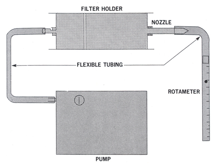
Attach the calibrated rotameter to the nozzle as shown in Figure S-3-3 and adjust the pump withdrawal rate to obtain isokinetic conditions.
Figure S-3-3: Schematic for adjusting sampling unit to isokinetic conditions
Description of figure S-3-3
Schematic for adjusting sampling unit to isokinetic conditions. Consists of filter holder, nozzle, flexible tubing, rotameter and pump.
Disconnect the rotameter and sample isokinetically for a known period of time. The optimum sampling time is that which gives a fibre loading of about five fibres per field for analysis. The sampling time can be estimated from Equation S-3-3, but the maximum sampling time shall not be greater than 2 h.
Equation S-3-3
ta = Ka / (f.a.) (Us) (Nd)2 (Cf)
where
ta = estimated sampling time, min (maximum 120 min)
Ka = constant, 27.69 mm2 ft in.2 fibres cm-3
f.a. = field area of counting field, mm2
Us = exhaust gas velocity, ft/min
Nd = nozzle bore, in.
Cf = estimated asbestos concentration in gas stream, fibres/cc
The first sample shall be a test sample to be analyzed to determine that fibre loadings are sufficient for counting without excessive masking by particulates.
During the sampling period monitor the exhaust gas velocity and if a drastic change is noted ( ± 15% of original velocity) adjust the pump withdrawal rate to maintain isokinetic conditions.
Do not sample during the time that the drill is moving to another hole, or during the time when extension rods are being removed from the completed holes. If necessary, it is permissible to sample in as many segments of time as required in order to get as close to optimum filter loading conditions as possible. If no estimate of the concentration is available, use 2 fibres/cc as first estimate.
Upon completion of sampling, turn off the pump and carefully remove the filter holder from the exhaust stream.
Maintain the exposed filter surface in the upright position, disconnect the pump and nozzle from the holder and seal the inlet and outlet.
Keep the sample in the upright position at all times during conveyance to the analytical laboratory.
Fill in the information on the data sheet (Figure S-3-4).
Figure S-3-4: Data sheet-drill baghouse sampling
| Filter number | Sampling rate (1 pm) |
Temperature (°C) |
Sampling time (min) |
Sample volume (1) |
Remarks |
|---|---|---|---|---|---|
S-3.3.5 Analysis
The filter samples are analyzed according to Method A-1 in Part II. Keep any unused sections of the filter in the holder, seal and store upright for future evaluation if necessary.