
Data Centre Services Reference Architecture Document (RAD)
Table of contents
1. Introduction
1.1 Purpose
The Data Centre Services (DCS) Reference Architecture Document (RAD) has been developed to describe the reference architecture models for a common, shared and consolidated DC environment for the Government of Canada (GC) as an enterprise. The DCS RAD defines the end-to-end architectural model and the components that will form the basis for developing the Shared Services Canada (SSC) target end-state DC services for the Data Centre Consolidation Program (DCCP). The architecture will support the delivery of DCCP services for SSC's partner organizations over the near term (less than three years), with an evolutionary capability to encompass a hybrid cloud service delivery model for long-term strategic planning.
1.2 Scope
This document is limited to articulating the conceptual data centre infrastructure architecture. The logical and physical architecture required to meet the intent of the conceptual architecture described in this deliverable is the subject of associated Technical Architecture Documents (TADs).
The target baseline security profile for SSC's end-state data centre services is Protected B, Medium Integrity, Medium Availability (PBMM). End-state data centres will also support workload profiles above PBMM (e.g. Secret) where required through appropriate safeguarding measures over and above those implemented for the PBMM baseline. Partner organizations are responsible for implementing application-level security safeguards over and above those implemented by SSC in its data centres in order to meet their particular information security requirements.
The security controls that are identified in this document are strongly influenced by Communications Security Establishment Canada's (CSEC's) Information Technology Security Guidelines (ITSG) publications. In addition, this document constitutes a key deliverable for achieving Security Assessment and Authorization (SA&A) and overall service authorization successfully. This approach will allow risk management groups to validate the compliance of each component's design and implementation with this document specification, thereby facilitating assessment efforts and accuracy.
The architecture is based on current concepts and technologies available within the data centre space. As the technologies and surrounding infrastructures evolve, the architecture will also need to evolve. The architecture presented in this document will set the standard for the target data centre services that will allow SSC to re-engineer, virtualize and consolidate DC services, and enable integration of various other partners and service providers.
This document covers the following topics:
- DC requirements,
- DC vision and target services,
- DC architecture models,
- DC service management.
Future releases of this document will elaborate on public/hybrid cloud computing architecture models, usage and integration with the GC community cloud, security profiles higher than PBMM, and partner organization applications.
1.3 Document Map
This RAD is an SSC design artifact that supports the transformation towards the target state of SSC's DC services. Throughout the document, a multi-layer architecture approach informs about multiple components, including infrastructure, toward the creation of a secure DC environment suitable for GC departments and agencies. This document describes an architectural approach to building the future DCs in a properly zoned and protected environment.
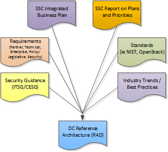
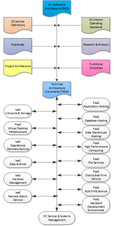
The document maps shown in Figure 1and Figure 2 illustrate the associated end-state deliverable reference documents that will form an evolving document container for RADs and TADs.
This document:
- takes a pragmatic and integrated delivery approach for planning, building and operating the DCs;
- provides traceability and direction in the creation of the TADs, Detailed Design Specifications (DDSs) and Build Books;
- provides a security by design view of the infrastructure elements and the service specific elements that support DC services; and
- identifies a security architecture that aligns with ITSG security guidelines, as well as the IT Shared Services Security Domain and Zones Architecture documents.
1.4 References
This section identifies reference material that has been utilized for the development of the DC Reference Architecture. Refer to Appendix B: References for a list of documents utilized for the creation of this RAD.
1.4.1 National Institute of Standards and Technology
The United States Government (USG) National Institute of Standards and Technology (NIST) Cloud Computing Reference ArchitectureFootnote 1(CCRA) establishes a common language for government and industry to describe IT services in a modern service delivery context. SSC Enterprise Architecture has validated the NIST CCRA as a viable way to describe SSC's own service offerings, as seen from the perspective of both the service provider (SSC) and the service consumer (partner organizations). The DC services presented in this document are described in a way that is consistent with the NIST CCRA.
There are four core documents that form part of the NIST CCRA:
- NIST SP 500-292: Cloud Computing Reference Architecture,
- NIST SP 800-145: The NIST Definition of Cloud Computing,
- NIST SP 800-146: Cloud Computing Synopsis and Recommendations,
- NIST SP 800-125: Guide to Security for Full Virtualization Technologies.
Further details on NIST CCRA are available at Publication Citation: NIST Cloud Computing Reference Architecture
1.4.2 OpenStack
OpenStack, an Infrastructure as a Service (IaaS) cloud computing project, is a cloud operating system that provides a flexible architecture to enable the convergence and provisioning of on-demand compute, storage and network resources for building highly scalable public and private clouds. Further details on the OpenStack cloud computing reference architecture are available at www.openstack.org. SSC is currently investigating how cloud operating systems such as OpenStack can be leveraged going forward.
2. Context
2.1 SSC Mission
In the context of service excellence, innovation and value for money, Shared Services Canada (SSC) is mandated to maintain and improve the delivery of IT infrastructure services while simultaneously renewing the Government of Canada's (GC's) IT infrastructure. SSC is bringing a true enterprise perspective to GC IT infrastructure, not just to improve service, but also to eliminate duplication and cut costs. An important aspect of that work is the development of enterprise-wide service standards, formerly established and maintained by each of the 43 partner organizations for their own environment, and now being developed collaboratively for the GC.
In collaboration with its partner organizations, and through the counsel provided by industry, SSC is identifying the IT infrastructure requirements of the government as an enterprise, and applying best practices to address its operational challenges and meet the government's modernization targets. Building a more robust foundation for modern government operations is also strengthening our ability to protect the information of Canadians.
2.2 Government of Canada Data Centre Environment
Today, the GC supports more than 400 data centres (DCs). These facilities were developed over many years in response to the independent service demands and requirements of individual departments and agencies. SSC's review of the existing DCs found that:
- service capacity varies greatly from one DC to another ‒ some have excess computing capacity that is unused, while others strain to meet demand;
- DCs are maintained with various levels of resources;
- many have outdated heating and cooling systems that are not energy efficient and require frequent maintenance; and
- most DCs have their own reliability and security standards, requiring multiple service teams and varying service contracts.
2.3 Data Centre Consolidation Program
The Data Centre Consolidation Program (DCCP) represents SSC's coordinated effort to rationalize and consolidate GC DCs, and to provide overall enterprise-wide service delivery management for its 43 partner organizations. The goal is to optimize the delivery of GC DC services by standardizing technologies, consolidating buildings and IT, centralizing operations, and re-engineering service delivery. This will reduce costs, improve service and security, and ensure the sustainability of GC DC services.
The DCCP will focus on the following DC elements: buildings, hardware, software, network and storage infrastructure, management and operation, security, brokerage, orchestration and provisioning capabilities. By implementing a comprehensive modernization strategy across all of the GC, the DCCP will deliver efficient, scalable and standardized DC services that will reduce operating costs for government DC services as a whole.
2.3.1 Vision
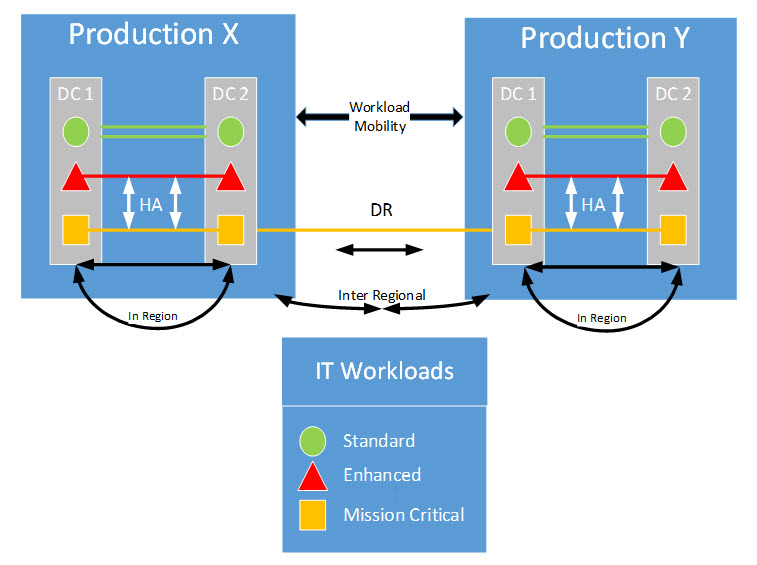
The DCCP vision includes the consolidation of more than 400 DCs to fewer than ten state-of-the-art facilities providing enterprise-class application hosting services. Data centres will utilize a secure containment strategy to host the workloads of partner organizations within a shared domain/zone configuration. Data centres will be deployed in a manner that provides partner organizations with High Availability (HA) and Disaster Recovery (DR) capabilities to support enhanced and mission-critical systems. The model defined to support this goal is referred to as a 2+1 Availability Strategy and will be accomplished through the operation of two DCs within a region forming a High-Availability pair (''Intra-Region HA''), with one DC outside the region providing Disaster Recovery (''Out-of-Region DR'').
DCCP will also provide SSC partner organizations with a set of defined target services that are coupled with advanced features of the underlying infrastructure in order to:
- provide a dynamic, "just in time" computing environment that meets the varied application and data processing needs of SSC partner organizations on an ongoing basis;
- establish a software continuum built up from elementary services through to full programmability and promoting a common application delivery model;
- adapt and evolve over time in a manner that aligns with ever-changing technological and market landscapes, without incurring penalties due to decisions made;
- leverage virtualization to drive consistency and standardization across platforms, thereby reducing overall complexity and related costs;
- support service model deployment innovation and cost savings through private-sector engagement; and
- enable online brokerage and orchestration services with the capability to leverage private, public and hybrid cloud computing services.
2.3.2 Strategic Approach
The SSC DC will represent a living model for GC IT facilities that will continuously evolve to meet the needs of citizens, the GC and an ever-changing IT technology landscape. SSC's objective in centralizing the management of DCs is to improve efficiency and reduce costs. Unused or underutilized assets will be shared to meet demand without incurring new costs. SSC anticipates receiving discounts by purchasing common hardware and software products and services in volume; ongoing savings will be realized on service contracts through consolidation and standardization. Finally, reducing the number of DCs will save on power and cooling, and improve security.
While DC consolidation will provide the GC with significant advantages in the near to medium term, the development of a dynamic and flexible sourcing strategy that leverages the capabilities of workload mobility, open standards and hybrid cloud computing resources will enable SSC to future-proof service delivery, with the ability to broker, orchestrate, provision, deliver and repatriate standards-based IT services from multiple sources.
2.3.3 Strategic Business Outcomes
The Data Centre Consolidation Program will provide the opportunity to achieve the following strategic business outcomes:
- Savings – Transformation, consolidation and standardization of DC services will realize material and ongoing cost savings through economies of scale and avoidance of future costs. These savings will be reinvested in the transformation activities. Savings will also be generated by a reduction in energy consumption and carbon footprint.
- Service – Transformation, consolidation and standardization of DC services will better enable the delivery of government services to Canadians by improving availability, scalability and agility of IT infrastructure services. Better services mean responsiveness to business demands and improved client satisfaction. Outcomes will be measured by realizing increases in capacity and speed, improved response times, and reductions in service calls and service outages
- Security – Transformation, consolidation and standardization of DC services will provide a secure technology infrastructure and environment to meet program needs, increase confidentiality and integrity of information, enable enhanced cybersecurity, and strengthen Canada's national security. Outcomes will be measured by realizing a reduction in vulnerabilities and security breaches, and improved audit findings.
2.3.4 Business Design Principles
In support of the outlined goals, principles have been adopted from the domain of IT as a business. These principles include:
- employing established ideas and concepts from service-oriented architecture: enhances business-IT architecture alignment by promoting a new design model that incorporates business logic into the IT designs;
- designing a rich, forward-looking platform supporting middleware and service-oriented application infrastructure;
- identifying and leveraging commonalities: enables economies of scale opportunities through the sharing of a single/common infrastructure and platform services; and
- new applications that should result in increased utilization of existing assets, not the acquisition of new assets.
2.4 Strategic Priorities
The following high-level strategic priorities have been defined for development of SSC data centre services:
| Priority | Definition | Strategic Requirement |
|---|---|---|
| Costs and Funding | Category relates to GC operating and capital expenditure needs and constraints | Development of a predictable and sustainable funding model, along with an open and transparent costing model, that support financial reporting back to stakeholders. Realized cost savings, efficiencies and modernization while reducing overall GC expenditures in long-term capital assets, including DC real property facilities. Reduced infrastructure and labour costs through standardization of DC services, including but not limited to, centralized administration and procurement of real property and IT assets, and IT asset-sharing across the GC to maximize resource usage. |
| Availability | Category relates to the availability and reliability of service expected from the infrastructure so as to support delivery of GC programs and services | Reduced risk to the GC through DC consolidation and provision of high-quality DCs supporting HA, DR and Operational Recovery (OR) capabilities through redundancy in facility capabilities, diversification and IT infrastructure renewal. Standardized, multi-tier availability levels across GC DCs to satisfy stakeholder business needs. Develop timely, priority-based response to service requests to meet new business demand, followed by timely, dynamic allocation of computing resources to meet variable computing demands. Offer a range of standard services, service levels and service level monitoring and reporting capabilities in order to meet the full variety of business needs across the GC. |
| Performance | Category relates to agility and the ability to react quickly to changing GC requirements | Utilize IT architectures to enable rapid provisioning of IT systems to meet the full variety of business needs across the GC. |
| Policy Compliance and Security | Category relates to compliance with GC's policies and regulations that are applicable to the DC services environment | Develop IT security architectures that leverage next-generation technologies while ensuring compliance with GC security and policies for the protection of data assets. |
| Strategic Alignment and Political Sensitivity | Category relates to the GC's business priorities and constraints with respect to DC services | Develop effective, efficient and innovative IT architectures that provide elasticity, scalability and rapid provisioning for multi-tenant service requirements. |
2.5 Data Centre Requirements
In consultation with SSC partner organizations and stakeholders, SSC has developed a consolidated set of requirements that have been utilized for the development of the SSC Data Centre Architecture. The requirements identified within Appendix A: Data Centre Requirements are high level. A more detailed list of partner requirements has been identified under Reference 1 ‒ Shared Services Canada, Data Centre Consolidation Summary of Requirements. Reference IDs for each requirement are utilized for the development of a Requirements Traceability Matrix (RTM), where architectural elements are mapped to the identified requirements (refer to TADs for further details).
3. Target Architecture and Target Services
3.1 Assumptions
The following assumptions are made:
- The Government of Canada (GC) is a single enterprise that will make use of a common, shared data centre (DC) and telecommunications network infrastructure.
- Applications will be migrated to the target architecture as part of the application lifecycle, either with new deployments or re-engineering of existing applications driven by partner organizations.
- Full traceability of Detailed Design Specifications (DDS) documents to the architectural requirements identified in the DC Reference Architecture Documents (RADs) and Technical Architecture Documents (TADs) will be possible.
- Various build groups will be able to provide full traceability via Build Books to the certifier before the solution goes into production.
- The Information Protection Centre (IPC) will collect, analyze and aggregate information from logs when required, and as part of their incident handling and investigation best practices.
- Data centre services in scope of this RAD will service SSC's 43 partner organizations, as well as clients from other government departments and agencies.
- Network connectivity between partners and clients and the new DC services will be provided through the common GCNet Inter-Building Network.
- Shared Services Canada (SSC) will develop the security profile for Protected B/Medium/Medium (PBMM) and socialize with partner organizations prior to production deployment.
3.2 Architecture Principles
Architecture principles are used to define the influencing rules and guidelines for development and deployment of an IT architecture. As such, the principles identified below have been used for development of the DC architecture:
- The five characteristics of cloud computing:
- On-demand self-service: provides the capability to enable dynamic resource allocation for the provision of computing resources based on consumer needs;
- Ubiquitous network access: provides 'anywhere on any device' broad network access capabilities to platforms and services through the use of either thick or thin client access methods, including desktops, mobile platforms and web browsers;
- Resource pooling: abstracts physical resources through virtualization, leveraging nodes of physical compute, storage and networking resources to securely and dynamically allocate virtual resource pools on demand, and vendor independence through common standards and Application Programming Interface (API);
- Rapid elasticity: leverages the capabilities inherent in self-service and resource pooling to provide the ability to grow and shrink capacity on demand (processing power, storage, network);
- Measured services: provide a capability to perform 'usage metering' and reporting;
- software defined DC/software defined networking;
- service orchestration with pervasive automation;
- resilient and fault-tolerant infrastructure;
- harmonized physical and virtual security controls;
- maximum sharing of resources and services – secure policy-based access controls;
- workload mobility across multiple provisioning channels through open standards.
3.3 Conceptual End-State
The following graphic depicts the conceptual SSC DC end-state architecture and associated capabilities.
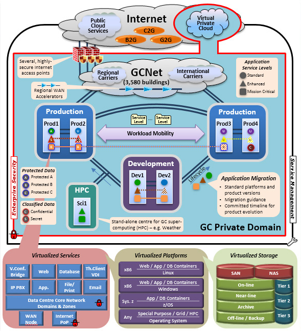
Enterprise Security
- All departments share one Operational Zone
- Domains and Zones where required
- Classified information below Top Secret
- Balance security and consolidation
- Consolidated, controlled, secure perimeters
- Certified and Accredited infrastructure
Service Management
- ITIL ITSM Framework
- Standardized Service Levels/Availability Levels
- Inclusive of Scientific and special purpose computing
- Standardized Application and Infrastructure Life-cycle Management
- Smart Evergreening
- Full redundancy - within data centres, between pairs, across sites
Consolidation Principles
- As few data centres as possible
- Locations determined objectively for the long-term
- Several levels of resiliency and availability (establish in pairs)
- Scalable and flexible Infrastructure.
- Infrastructure transformed; not "fork-lifted" from old to new
- Separate application development environment
- Standard platforms which meet common requirements (not re-architecting of applications)
- Build in security from the beginning
Business intent
- Business to government
- Government to Government
- Citizens to Government
3.4 Target Architecture
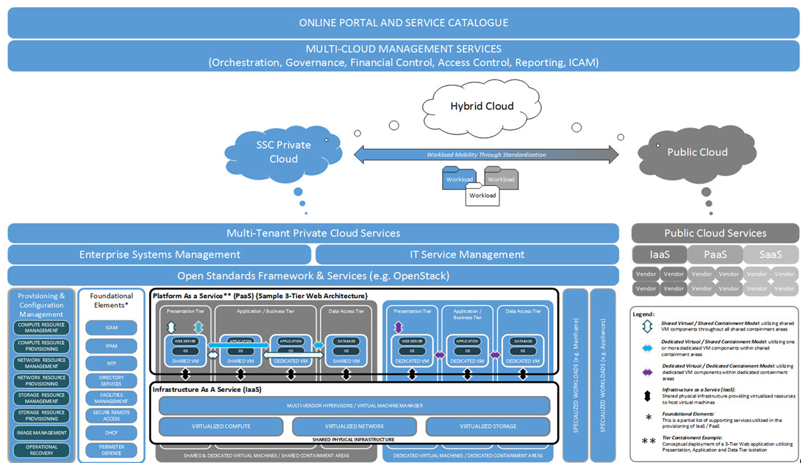
Figure 4 illustrates SSC's multi-tenant cloud computing conceptual target architecture; it will provide SSC partner organizations with an online portal, service catalogue and multi-cloud management services (orchestration, governance, financial control, reporting and identity, credential, access management). The target architecture utilizes a unified enterprise service management framework coupled with open standards to enable a vendor-agnostic capability to provision, configure and manage virtual machines and workloads within a secure containment architecture.
Criteria for the placement and/or mobility of workloads within either a private, public or hybrid cloud infrastructure will be key to a successful multi-cloud implementation strategy. Such criteria will include:
- workload security profiles;
- service level requirements;
- degree of specialization and technical uniqueness;
- skillset to support workload (inhouse versus outsourced);
- commercial availability of compatible hosting solutions; and
- capability of workloads to move between public and GC private clouds versus remaining on GC-controlled infrastructure.
3.5 Target Data Centre Services
The SSC Service Catalog will be the primary interface to meet the IT requirements of partner organizations. In concert with service-level requirements, the Service Catalog shapes IT service delivery to partner organizations.
DC service offerings that will feed an overall SSC Service Catalog are grouped into two major categories: Partner-Facing Services and Enabler Services, and are described in the following sections.
3.5.1 Partner-Facing Services
The core DC service offerings are "Platform as a Service" (PaaS) based hosting services, which are to be used by partner organizations which require a complete and managed platform service to run their applications and databases. PaaS services provide everything under the partner organization application (guest workload), including standard platform middleware, OS and database. The virtualization layer and underlying infrastructure is provided by DC Enabler Services for compute, storage and network, and the physical hardware and DC facilities.
Partner-Facing Services include:
- Application Hosting,
- Database Hosting,
- Data Warehouse Hosting,
- High-Performance Compute Hosting,
- File Service (GCDrive),
- Distributed Print,
- Bulk Print,
- Standard Development Environment.
The following provides a high-level overview of planned Partner-Facing DC services.
- Application Hosting (PaaS) – provides a standardized PaaS for partner organizations' Commercial Off-the-Shelf (COTS) and consumer-built applications. The service includes a three-tier managed application platform with standardized database and platform middleware (Windows, J2EE and LAMP), as well as full management of "everything but the application." An optional version including only a managed OS platform is offered on a case-by-case basis. The above platform service options reside on SSC's standard secure managed computing, storage and network infrastructure, allowing partner organizations to provision their own application and virtual infrastructure resources. Both are complemented by SSC's support services, with the added benefits of virtualization in SSC's secure and robust DCs.
- Database Hosting (PaaS) ‒ provides a standard solution specific to the needs of partner organization databases. The PaaS includes middleware and tools for leading databases, residing on SSC's standard managed computing and storage infrastructure. Partner organizations can now provision their own databases and virtual resources. The service resides on SSC's standard secure managed computing, storage and network infrastructure, allowing partner organizations to provision their own database and virtual infrastructure resources. The service is complemented by SSC's support services, with the added benefits of virtualization in SSC's secure and robust DCs.
- Data Warehouse Hosting (PaaS) ‒ provides a standard PaaS solution to partner organizations for data mining, query and reporting with historical data from the transactional data. The service includes the suite of ETL (Extract, Transform and Load) to move the transactional data to the data warehouse hosting platform. Complimented by business intelligence tools, including but not limited to data mining, text mining, reporting, querying and data visualization.
- High Performance Computing (PaaS)– provides a standardized and fully managed High Performance Computing (HPC) platform for consumers with extreme performance computing needs. The basic service is suited for intermittent computing needs and supports self-service provisioning. The enhanced HPC service is for steady state-heavy computing demands and added supporting services for specialized configurations. SSC provides lifecycle management for everything but the consumer workload.
- File Service (GCDrive) (PaaS) – provides a centralized, highly scalable, secure online storage solution for unstructured data and files. File service allows users to store, access and share files from a virtual file server anywhere on the GC network, without having to know the physical location of the file. Service provides:
- virtual storage up to the allocated amount of space described in the service consumption metrics;
- data moves and migration;
- fully managed service including all levels of support;
- anti-virus protection;
- automated daily backups with offsite archival storage ‒ restore services;
- management and configuration of the users' accounts.
- Distributed Print Service (SaaS) – provides a fully managed printing service where users can print efficiently and securely, and coordinate all activities related to printing services on a GC network and in the Government of Canada Community Cloud (GCCC). Users are provided with self-service print management to associate printers with their user account, select the printer and printer properties for each print job, and receive updates regarding job status and progress. The service includes centralized monitoring and management of policies, printers and consumption; providing alerts and analytics for optimal productivity; and cost efficiency.
- Bulk Print (SaaS) – provides a standardized and fully managed print service for consumers requiring very high volume and specialized print media, with high-volume distribution and mailing capabilities in secure, centralized printing facilities.
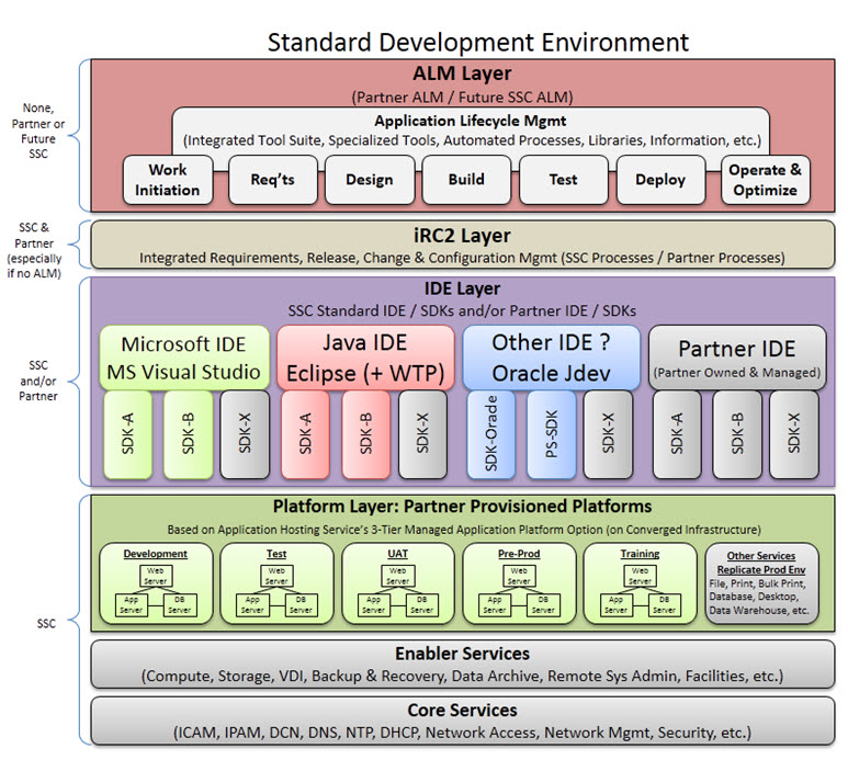
- Standard Development Environment (SDE) ‒provides a platform service for partner organizations developing or maintaining business systems for SSC's standardized cloud-based environment. An optional standard transformation capability and toolset is provided for transforming mature business systems (legacy) to run in SSC's standardized cloud-based environment. Both of these offerings are provided from SSC's secure and robust development facilities. Similar to the supporting services included with SSC's partner-facing offerings, development support services provide an approach specific to the demands of systems development (e.g. less stringent service levels, a Systems Development Lifecycle (SDLC) emphasis on technical support and professional services, etc.).
3.5.2 Enabler Services
These enabler services underpin DC partner-facing services by providing complete and managed infrastructure services as a foundation to all of the above PaaS-based services SSC provides to its partner organizations. Shared Services Canada uses these internally facing enabler services to deliver partner-facing services. Partner organizations will only be able to subscribe to enabler services under special circumstances and through the official SSC exception process.
Enabler services include:
- Compute and Storage Provisioning,
- Virtual Desktop Infrastructure,
- Operational Recovery Service,
- Data Archival,
- Facilities Management,
- Remote Administration.
The following provides a high-level overview of planned enabler services.
- Compute and Storage Provisioning (IaaS) ‒ provides a highly available, secure and fully managed capability for computing and storage. Compute provides a fully managed virtual infrastructure platform with container isolation for guest OS and workloads (physical bare-metal and virtual machine). Storage provides various levels of data protection, data availability and data performance, in a highly available online data repository. Storage infrastructure provides both block-level and file-level capacity in the form of Storage Area Network (SAN) and Network Attached Storage (NAS) respectively.
- Virtual Desktop Infrastructure (PaaS) ‒ provides a fully managed platform service for hosting virtualized desktops and common office applications, enabling Desktop as a Service, thereby allowing users to access their full featured virtual desktop and applications from anywhere, using various devices. The service provides significant Total Cost of Ownership (TCO) savings and rapid provisioning for users.
- Operational Recovery Service (IaaS) – provides storage capacity for copies (backup) of data used for point-in-time data and system recovery in the event of failure or loss. The backup service makes use of redundant SAN technologies and interacts with the compute and storage provisioning service.
- Data Archival (IaaS) – provides secure storage of older or less utilised data, for longer-term retention. Archived data are indexed and accessible by business users. The Archive Service makes use of redundant SAN technologies and interacts with the compute and storage provisioning service.
- Facilities Management Service (IaaS)– provides management of the physical assets for building space, security, power, backup power, climate, fire and cable plant as well as external co-location services. Also provides hands-on support services to other enablers (onsite feet on the ground).
- Remote Administration (IaaS) – provides SSC system and partner-application administrators the ability for remote access (part of the overall Service and Systems Management capability).
3.5.3 Service Interdependencies
As elaborated within Section 3.5.1 and Section 3.5.2, the DC Reference Architecture includes both DC partner-facing and enabler services. The delivery of such services is dependent upon supporting services that are common across all service offerings (foundational elements). The following table provides a service dependency mapping for partner-facing and enabler services, as well as foundational elements.
Table 2 : Data Centre Reference Architecture Document Service Interdependency Mapping
3.6 Integrated Data Centre Business and Technology Platforms
The SSC DC architecture is built upon three principle hardware components: compute, network and storage. Through the arrangement of these three components and the layering of software on top, useful services can be rendered. These services represent a technology platform on which GC IT workloads are executed. In addition to the technology platform, there is a business platform responsible for partner-facing service delivery. The business and technology platforms draw on concepts from "cloud computing" to exhibit the desired five characteristics: on-demand self-service; ubiquitous network access; resource pooling; rapid elasticity; and measured services. The following diagram illustrates the conceptual model of a cloud DC, from which the elements will be projected onto the SSC DC.
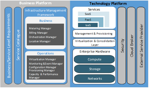
The business platform enables the delivery of IT-as-a-service, while the technology platform leverages the three architectural components (compute, network, storage) to render three basic service delivery offerings: Infrastructure-as-a-Service (IaaS), Platform-as-a-Service (PaaS) and Software-as-a-Service (SaaS). The business platform provides the framework for IT business alignment incorporating business drivers that are leveraged against the technology platform.
The framework consists of:
- business- and service-level requirements to meet the needs of partner organizations;
- target services from which partner organizations select those IT services they require; and
- an infrastructure management framework to provide both feedback to the business user and direction to the technology platform influencing IT service delivery.
The technology platform provides the framework for delivering IT-as-a-service to consumers. Characteristics of that delivery are influenced by the business platform. The technology platform framework incorporates:
- infrastructure, platform and software services consumed both internally by SSC organizational units and externally by partner organizations, supporting IT application delivery to end users;
- supporting infrastructure and processes enabling infrastructure and platform services, including:
- management and provisioning of services,
- virtualization and consolidation of baseline enterprise elements, and
- enterprise compute, network and storage resources;
- security services that will provide secure workloads enabling the confidentiality, integrity and availability of services.
4. Data Centre Architecture Models
4.1 Data Centre Facilities
The data centre (DC) facilities strategy is to reduce from more than 400 DCs to fewer than ten state-of-the-art Tier III (Uptime Institute standard) facilities enabling the provision of enterprise-class application hosting services. Data centres will be deployed in pairs within a geographic region defined to allow for real-time failover and synchronous data replication.Footnote 2 There will be one pair dedicated for non-production (development) workloads and two or more pairs for production. The two production pairs will be geographically separated to provide Disaster Recovery (DR) services in case of prolonged regional outages. Each production DC will have capacity to host in-region High Availability (HA) requirements ("enhanced'' service level profile), as well as capacity to host out-of-region DR requirements ("Premium'' service level profile). All production and development DCs will operate in a "lights-out'' manner, where no human interaction inside the DC secure space will be allowed outside of pre-approved, limited installation and maintenance activities.
4.2 Data Centre Infrastructure Architecture
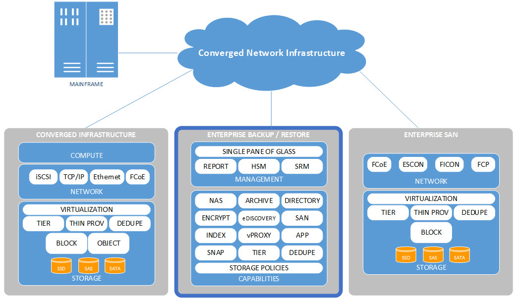
This section provides a high-level description of the target DC Infrastructure Architecture. Both Converged Infrastructure (CI) concepts and components, including compute, storage and networking, as well as discrete Enterprise mainframe, midrange and storage platforms are described. The following graphic illustrates the high-level architectural components of the DC Conceptual Architecture, which are further described in the upcoming sections.
4.2.1 Converged Infrastructure
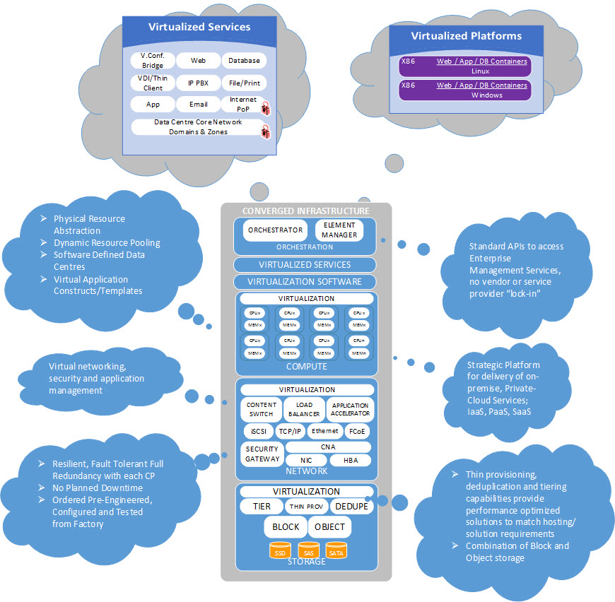
Converged Infrastructure is the name generally used to describe a pre-engineered set of servers, storage, networking and security systems that are integrated into shared pools of interoperable resources and managed through a common management and orchestration platform. While CIs can be deployed as bare-metal servers, in most cases the physical components are virtualized using hypervisor technologies. The result is a highly automated, cost-efficient infrastructure with the ability to respond quickly to changing business requirements without the need to physically reorganize infrastructure that is already deployed, or acquire new infrastructure. The CIs are sized and deployed based on templates that allow for implementation and growth with a predefined approach. This removes the planning and configuration burdens of traditional deployments and the heavy reliance on human interaction during the provisioning phase. The simplified architecture accelerates deployment of new capacity, provides greater flexibility of services and increased efficiency of deployed capacity, while lowering operational risks. Converged Infrastructure provides a blueprint for the DC to accelerate the provisioning of services and applications, and will be utilized to deploy the large majority of workloads within each Shared Services Canada (SSC) DC as the infrastructure of choice. Figure 8 illustrates the various benefits and capabilities of components within a CI.
Converged Infrastructure that is used to host the large majority of partner workloads (e.g. common J2EE, .Net, Commercial off-the-Shelf (COTS) Application Hosting) is referred to as the "general purpose platform,'' contrasted with "special purpose platforms'' that are geared to particular needs not well suited for the general purpose platform (e.g. high performance computing, mainframe, VoIP Gateway Appliance).
4.2.2 Compute Infrastructure
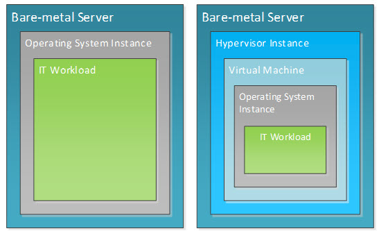
The compute infrastructure provides containers in which IT workloads run. An IT workload stack consists of an application, associated data and an operating system environment in which the application executes. A workload container is the pairing of compute infrastructure and an operating system environment. There are two kinds of compute infrastructure containers – a bare-metal (physical) server and a virtual machine. Figure 9 illustrates these compute infrastructure components in context. As can be seen, the bare-metal server is the basic building block of the workload container.
The compute infrastructure is implemented using a stateless compute node model where compute, storage and networking are assembled in a software-defined fashion to provide dynamically configurable compute infrastructure containers.
4.2.3 Storage Infrastructure
The storage infrastructure (within the CI or as part of an Enterprise SAN) provides capacity, connectivity, availability and data protection for IT workloads in which an application executes. In other words, storage is seen as an enabling service for compute. The storage infrastructure provides both block-level and file-level capacity in the form of Storage Area Network (SAN) and Network Attached Storage (NAS) respectively. Storage as an enabling service offers various levels of data protection, data availability and data performance based on cost and requirements for the organization as a whole.
The storage architecture will be deployed within the CIs and as traditional enterprise storage servicing the entire DC itself. Traditional enterprise storage will provide additional capacity for the CIs where required (i.e. overflow capacity), and to store large data repositories such as video, backups and big data that might not be well suited for CI storage. Traditional enterprise storage will also be used by non-CI servers such as mainframes, and also as the main repository for enterprise backup/recovery and data archival services. Figure 10 represents a conceptual view of the storage service model.
Block level access is to be used for applications that require high Input/Output per Second (IOPS) and availability. File level access is to be used for Common Internet File System (CIFS) and Network File System (NFS) file shares. Commonly, file storage is implemented in the form of a gateway appliance that connects to externally attached back-end block storage. File storage is used primarily for unstructured user data, and possibly even virtual hosts installed on NFS partitions, due to its high scalability and ease of management
Storage optimization techniques will be deployed to reduce cost and improve performance. These will include:
- Data De-duplication: reduces storage by eliminating redundant copies of data by retaining only one unique instance with only the change delta for all other copies. This method is very efficient in cases where there are multiple instances of the same data within the environment. For this reason, it will be implemented within the virtualized server environments as well as leveraged for data stores for applications without native data reduction tools. Effectiveness of the de-duplication method is reduced in environments where data is unique by nature (e.g. video streams).
- Thin Provisioning: an abstraction technique where the storage array allocates physical storage to a Logical Unit Number (LUN) from a common storage pool only when data is written to that pool. This technique will ensure the minimum amount of unused space is allocated to the clients. However, this technique could be affected by the type of operating and file systems that are utilizing the storage.
- Automated Storage Tiering: moves data blocks across multiple storage media without impact to hosts accessing the storage, in order to align the performance requirements to the storage media capabilities. Data blocks that are accessed more frequently are relocated onto faster, more expensive media, while infrequently accessed data blocks are placed onto slower and less expensive media. This entire process is transparent to the end client.
- Storage Virtualization: can be implemented through any of the primary storage layers with network- or controller-based architectures gaining prominence in recent times. Lack of intrusiveness of the virtualization solution needs to be one of the primary considerations when choosing an appropriate virtualization technology. By avoiding virtualization technologies that strip data packets and add their metadata into that packet, SSC will prevent being locked into a particular virtualization technology.
4.2.4 Data Centre Network Footnote 3
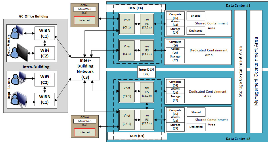
Figure 11 illustrates the overall GCNet and Data Center Network (DCN) high-level architectural components and position within the SSC DCs in terms of the major architecture blocks, DC components and their relationship. The DCN is the foundation for all DC services, and provides the transport infrastructure and connectivity between all components within the DC (intra-DCN), security services and interconnectivity to external networks. The inter-DCN is an overlay network that leverages GCNet to provide connectivity between facilities.
The DCN architecture described within this Reference Architecture Document (RAD) relates to the virtual networking within the compute infrastructure and access layer switching included with the CI. Each CI (compute, access, storage) architecture includes the physical layer 2 access switches required to connect all the compute and storage components and virtualized networking and security. These access switches are then connected to the upstream DCN infrastructure for layer 3 connectivity, advanced services (e.g. Application Delivery Controller (ADC), external firewalls, etc.). Switching components within the CIs provides connectivity between compute components and storage services.
| Component Identifier | Component Name | Component Description |
|---|---|---|
| C4.1 | Core Connectivity | DCN connectivity services provide the foundation on which departments and agencies will be provided controlled access to applications/services hosted in the GC community cloud. |
| C4.2.n | Perimeter Security | Provides security perimeter services for containment areas. Instances of C4.2 are labeled as sub-components of C4.2 (e.g. C4.2.1, C4.2.8). |
A large portion of the network and security segregation will be performed within the hypervisors. All inter-server communications will be achieved through virtual networking and firewalls to restrict unauthorized flows. Unlike traditional deployments that have all security performed on physical devices, virtual networking and firewalls will allow filtering to be implemented on flows between Virtual Machines (VMs) within the hypervisor. Three deployment models will be used.
- Virtual Deployment Model (Default): fully virtualised where all components are deployed within the hypervisor. The DC architecture is developed to accommodate primarily virtualised workloads. Under the virtualised model, network and security separation of workloads are contained within the hypervisor. This allows servers within different zones to communicate without leaving the compute layer; provides a single communication point for users' access to devices within the Public Access Zone (PAZ) or Operational Zone (OZ); and enables restricted access to backend application and database servers. The presentation server will respond to user requests through an interface that provides network access either through a firewall or directly. All backend communication between the presentation application and data layers will be achieved through private networks secured by security devices.
- Physical Deployment Model: fully physical to accommodate bare-metal deployments. Workloads deployed on bare-metal deployments and/or purpose-built appliances will follow the same communications paths as within the virtual environment. Because most bare-metal installations do not contain virtual network and security components, they will be provided by the physical DCN infrastructure
- Hybrid Deployment Model: workloads are both virtual and physical. The hybrid approach will leverage a combination of the above options to accommodate solutions developed with both virtual and physical workloads
4.3 Data Centre Platform Architecture
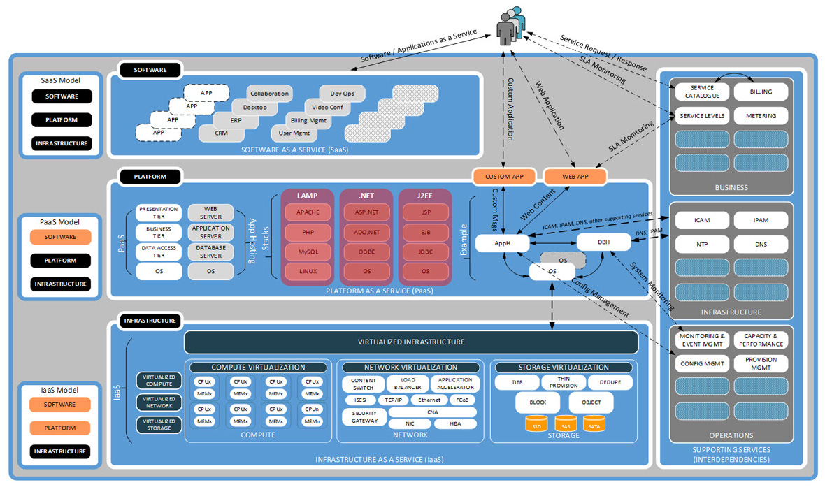
As illustrated in Figure 12, Platform as a Service (PaaS) will leverage enabling services from Infrastructure as a Service (IaaS) components (compute, networking and storage) and supporting services (i.e. PMI, IPAM, DNS, etc) to provide PaaS service offerings, such as application hosting and database hosting.
Figure 12 depicts an example of application hosting components that may be provided as part of the Application Hosting (AH) service offering, and references three sample AH "stacks" (LAMP, .NET, J2EE). Interoperability occurs between IaaS and all tiers of the PaaS service offering (OS, database server, application server, web server) and supporting DC services, including business, infrastructure and operations services. Further details are available within the associated IaaS and PaaS Technical Architecture Documents (TADs).
4.4 Data Centre Availability
For the purposes of this document, DC availability includes High Availability (HA), Disaster Recovery (DR) and Operational Recovery (OR). Disaster Recovery and HA generally refers to continuity of operations in the event of an outage, while OR refers to the ability to recover both data and operations to a known good working state such that business operations may resume.
4.4.1 High Availability
High Availability provides DC service protection within and across DCs in the same geographic region, using various techniques such as automated failover, clustering and synchronous replication at the network, platform and storage layers. Disaster Recovery refers to DC service protection that is provided out of region and across DCs, using replication technologies such as platform-based replication and asynchronous storage-based replication.
DCs will be deployed to provide both HA and DR solutions to the end systems that are deployed within. The default model defined to support this goal is referred to as a 2+1 Availability Strategy. The deployment of this 2+1 Availability Strategy will be accomplished through the operation of two DCs within a region forming a HA pair (''Intra-Region HA''), with one DC outside the region providing DR (''Out-of-Region DR''). The geographical limit placed upon intra-regional DC pairs is established by technological constraints on synchronous data replication and application response time latency. Because of this, another availability strategy will also be utilized where HA is provided within one DC (''Intra-DC HA''), with one DC outside the region providing DR. There is no practical geographical limit placed on inter-regional DCs.
Intra-R egion and Intra-DC HA design is driven by extremely stringent service recovery time objectives and data recovery point objectives, whereas inter-region DR design is driven more by survivability of mission-critical applications in case of large regional disaster situations rather than individual DC outages.
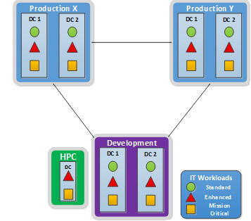
As illustrated in Figure 13, three generic service level profiles will be available:
- Standard, where services will be provided through a single DC, with local system redundancies built in, but no advanced HA capabilities (e.g. synchronous data replication);
- Enhanced, where services will be provided through two DCs within a region (default) or one DC (optional) with advanced HA capabilities (e.g. synchronous data replication);
- Premium, where services are deployed with an out of region DR capability over and above the "Enhanced" capability.
4.4.2 Disaster Recovery
For the DR component, a pair of DCs will be located at an Inter-Regional location, at a distance in excess of 1,000 kilometres from the other pair. Providing DR at this distance is a standard practice in order to mitigate against any widespread regional disasters that might occur. A DC in one region will provide bidirectional replication to an alternate DC in another region for DR purposes.
For the HA pairs, synchronous storage array-based replication will be used for workloads that have a Recovery Point Objective (RPO) of zero. Synchronous storage array-based replication provides the fastest and most reliable form of data replication known today. For greater distance, asynchronous replication will be used. Asynchronous replication leverages IP as the transport and has an RPO greater than zero, but is far less expensive than synchronous storage array-based replication. Asynchronous replication can support virtually unlimited distances.
There are various implementation options to achieve HA/DR, including storage array-based replication, database- or host-based replication, and application-based replication. Each implementation option has its own advantages and disadvantages, specifically related to cost and performance. For example, array-based replication is the most costly but provides the greatest performance and availability, while host-based replication is lower in cost and performance benefits compared to array-based replication. The various methodologies will be described in further detail within the various DC Technical Architecture Documents (TADs). It must be noted that, gradually in the coming years, applications ‒ whether developed inhouse or commercially ‒, will be developed with cloud-aware capabilities that assume an ''unreliable'' underlying platform and infrastructure. In other words, applications will be able to call up cloud resources directly from different sources to compensate for unreliable underlying services. This should reduce the need to build in complex and costly HA capabilities in the infrastructure over time.
Figure 14 illustrates the HA/DR configuration.

4.4.3 Operational Recovery
Operational Recovery, also known as Backup and Recovery, provides a capability for copies (backup) of data to be used for point-in-time data and system recovery in the event of failure or loss.
Traditionally, backups were performed on a nightly basis, providing clients with the maximum RPO of 24 hours. As technologies have evolved, RPO levels have decreased to the point where today's technologies enable organizations to operate without data loss. In addition, technologies have evolved to minimize the Recovery Time Objective (RTO) values and bring those in line with organizational requirements.
Typically, OR solutions are software-based and can leverage commodity compute, storage and network infrastructure, whether as part of a CI solution or as a traditional enterprise backup and recovery solution deployment. Therefore, it is possible and desirable to modularize this strategic capability to define an OR architecture independent of the underlying infrastructure; while most CI solutions have backup and recovery capabilities included, a unified OR strategy will be deployed to enable backup and recovery capabilities across all DC infrastructure components, including CIs and Enterprise SANs.
In the proposed OR architecture, the production CI will leverage block-based snapshot functionality for retention of data less than a week old. The snapshots will be stored on the production CI, which will provide the quickest recovery capability. Based on the requirements of SSC partner organizations, snapshot copies of mission-critical data could be taken as often as every half hour, with data retention timeframes defined by coordinated storage policies. This capability will allow for the most flexible recovery capability while limiting demand on capacity requirements.
Dedicated backup CIs and enterprise SANs may be used exclusively by the OR service as repositories for backed-up data, and will be used to perform data restores for data that has been modified more than one week ago, or in the event that a primary CI has been compromised (e.g. storage array failure). Data will be backed up on a scheduled basis, and retained on the backup CI for a prolonged period (e.g. 30 days), at which point the data will be overwritten. During this rolling 30-day period, an identical copy of the data will be replicated to an alternate site for an additional layer of data protection in the event of a site failure or corruption on the primary site's backup CI storage array.
4.5 Infrastructure and Application Lifecycle Environments
This section provides details on IT lifecycle environments that will be supported by SSC.
4.5.1 Lifecycle Process
Innovation is an iterative process initiated by the perception of a new product or service opportunity for a technology based invention that leads to development and production where the end goal is the realization of some value. SSC supports this process by providing sandbox environments (directly or through industry partnerships), where new candidate ideas and technologies can be investigated and tested for suitability and potential value. Promising candidate technologies migrate from the sandbox to development environments. In the development phase, additional activities occur to transform the technology into something repeatable, useful and verifiable. Upon successful completion of development, the technology migrates to a production environment for use by the end consumers.
SSC DCs support the development and production phases of the innovation process by providing a baseline implementation of a standard development environment aligned with its intended use. Additional environments may be included on an exception basis to meet specific program requirements.
4.5.2 Infrastructure/Service Development Environments
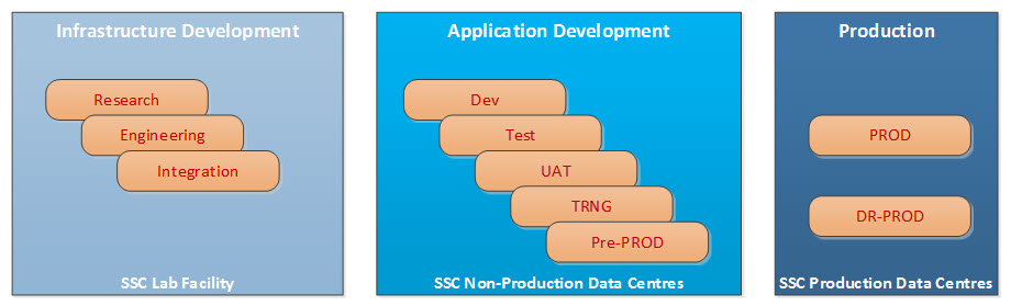
Infrastructure/Service Development typically involves physical hands-on activities that are not suited to lights-out production DCs, and therefore will be carried out in appropriate environments in end state data centres. The Infrastructure/Service Development area will support the following three distinct activities, each with its own environment:
- Research: evaluate new vendor products, technologies and deployment models in order to determine their feasibility and value proposition.
- Engineering: the engineering environment will be leveraged to develop Build Books, and test configuration changes on individual components and solutions coming from the research phase or other initiatives.
- Integration Testing: This environment is a replica of the production SSC DC infrastructure to enable certification, verification and diagnostic activities. The testing of new hardware and software releases of currently deployed products and newly engineered solutions will be completed within this environment to mitigate risks before being deployed within Application Development and production environments.
New features, technologies and/or software images will go through the Infrastructure/Service Development lifecycle to be deemed production ready. Once this has been completed, they will be deployed into the development DC infrastructure, followed by production.
4.5.3 Application Development Environments
Application Development Environments are completely separate from production environments and allow departments and agencies to develop and test new and/or redesigned applications. As part of the application lifecycle, there will typically be five sub-environments for the development of new applications. Based on requirements, and on an exception basis, additional environments may be added or removed, depending on program needs. The baseline sub-environments are:
- Development: this is used for development and basic testing of new applications and features. The applications are deployed to confirm functionality before introducing network segmentation and security.
- Test: as with the development environment, the test environment allows the developer to confirm the basic functionality of an application, but deployed in a production-like model that includes, for example, network segmentation and security.
- User Acceptance Testing (UAT): the UAT environment is where selected users test the applications before they are deployed into production. Applications already in testing are usually one release ahead of production.
- Training (TRNG): the training environment allows programs to provide user training on new applications or added features before being released.
- Pre-Production: this environment is a replica of the partner organizations' production applications and target production DC services and infrastructure; it enables certification, verification and diagnostic activities to be performed in an environment that mirrors the behaviour of the production environment.
The Application Development Environments constitute the steps or gates that applications may pass through in order to be released into production. To optimize the use of SSC DC infrastructure, engineering and support resources, as well as to enable consolidation and rationalization of DCs, it is important that partner organizations agree on standardized requirements for the type and number of environments. Without this, customized environments will emerge that require more resources.
4.5.4 Production Environments
The production DCs host the applications used by departments and agencies for day-to-day business. Workloads deployed within production environments can be deployed either in a single location or across a HA pair, depending on business requirements. Further application availability is provided through geographically diverse production DCs for disaster recovery.
4.5.5 Standard Development Environment Overview
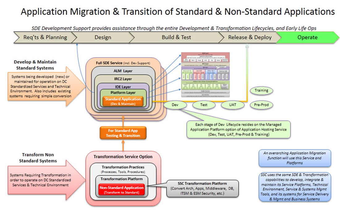
The Standard Development Environment (SDE) service is an enterprise approach that addresses the objectives of IT lifecycle management. The environment supports both an agile and responsive capability to support changing client needs. Benefits include improved provisioning, innovation, portability, test migration and SSC expertise to assist through the development and transformation lifecycles.
SSC will provide two capabilities within the SDE, as follows:
- Development and Maintenance will provide a platform service for partner organizations developing or maintaining business systems for SSC's standardized cloud-based environment;
- optional Application Transformation will also be provided for transforming mature (legacy) business systems to run in SSC's standardized cloud-based environment.
Both of these offerings will be provided from SSC's secure and robust Development Data Centres. Each capability will include support services similar to those of SSC's other services, but with an approach tailored to systems development (e.g. less stringent service-level targets, a SDLC emphasis on technical support and professional services, etc.) SSC will use the same SDE platform for the development, engineering and maintenance of its own service platforms, and internal business and service management systems.
4.6 Data Centre Security Architecture
Transformation, consolidation and standardization of DC services will provide a secure technology infrastructure and environment to meet program needs, increase confidentiality and integrity of information, enable enhanced cyber security, and strengthen Canada's national security. Outcomes will be measured by realizing a reduction in vulnerabilities and security breaches, and through improved audit findings.
This section examines the utilization of virtualization technologies within the DC architecture through the application of secure containment and Communications Security Establishment Canada (CSEC) security standards.
4.6.1 Security Standards
CSEC provides guidance regarding IT security standards for the Government of Canada (GC) through the publication of security guidance documents, including ITSG-22, ITSG-33 and ITGS-38. In addition, IT standards for virtualization are available from Canada's allies, including the National Institute of Standards and Technology (NIST) and CPA Security (refer to Appendix B: References for further details). SSC's DCs will be built and maintained to these standards to facilitate implementation of partner organization programs.
4.6.2 Security Controls
Within the realm of IT security, security controls define safeguards and countermeasures that minimize, counteract or avoid IT security risks. The following table identifies three security classes (technical, operational and management) and their associated family control types that will form part of the reference and technical architecture design. While the controls are grouped into three categories, the underlying implementation of any control may blur these boundaries. For example, the operational controls within media protection may involve a technical control implementation of cryptography to achieve the control.
| Security Class | Class Description | Control Family Types |
|---|---|---|
| Technical | Controls that are implemented and executed by information systems primarily through security mechanisms contained in hardware, software and firmware components |
|
| Operational | Controls include information system security controls that are primarily implemented through processes executed by people |
|
| Management | Controls include security controls that focus on activities for the management of IT security and IT security risks |
|
4.6.3 Security Requirements
The specification of security requirements along with their implementation will be documented in Service Definitions, Technical Architecture Documents (TADs), Detailed Design Specifications documents and Build Books, as per SSC implementation of ITSG-33's Information System Security Implementation Process (ISSIP). Refer to Section 1.3‒ Document Map for further details.
4.6.4 Data Centre Security Model
Whenever and wherever possible, the DC will utilize security services from the telecom and cybersecurity programs within SSC to implement the bulk of the technical controls listed above. As illustrated in Figure 8: Converged Infrastructure, security services (including firewall, Host Intrusion Detection/Prevention Systems (HIDS/HIPS), Network Intrusion Detection/Prevention Systems (NIDS/NIPS) and anti-virus) will be made available for partner use. These services will undergo their own security assessment and authorization processes in advance of DC services themselves.
4.6.5 Secure Containment Architecture
Before the creation of SSC, each government department typically maintained its own individual DC services deployments. The Data Centre Consolidation Program (DCCP) strategy for deploying DC services within SSC is to utilize secure containment areas within a single infrastructure to host all partner organizations' workloads. Dedicated DC infrastructure components will only be deployed where the business and security requirements of the partner organization justify, with appropriate governance and business case support.
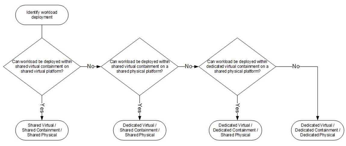
The ability to consolidate workloads into a Shared Physical Infrastructure Model will enable the consolidation of 43 separate partner DCs into a single GC environment. There are three configurations that result in utilization of a shared physical infrastructure, with an additional configuration reserved for partner organizations that can justify the need/use of a dedicated physical infrastructure.
These options are:
- Shared Physical Infrastructure:
- Shared Virtual/Shared Containment Model: (default) deploy partner organizations' workloads on shared virtual platforms and consolidate workloads within shared containment areas.
- Dedicated Virtual/Shared Containment Model: In instances where partner organizations' workloads cannot (should not) be deployed within the same virtual platform but can still reside within a shared containment area, a dedicated virtual platform would be created.
- Dedicated Virtual/Dedicated Containment Model: in instances where partner organizations' workloads cannot (should not) be deployed within the same containment area, a virtual/dedicated containment area would be created.
- Dedicated Physical Infrastructure:
- Dedicated Virtual/Dedicated Containment Model: for partner organizations with specific security requirementsFootnote 4 that cannot be addressed by either of the above shared physical models, a separate and dedicated physical infrastructure will be used. Requirements for dedicated infrastructure need to be supported by a business case and approved by the appropriate governance bodies.
Figure 19 identifies the containment area selection process that will be utilized to identify how workloads will be deployed.
Figure 19 : Containment Area Selection
Each containment area will be divided into zones based on CSEC's ITSG-22 Security Guidance, Network Security Zoning and SSC's Secure Domain and Zones Architecture. Figure 20 illustrates the zones that will be deployed within each physical and virtual containment area. Partners will be provided with a Public Access Zone (PAZ) for external-facing presentation servers, an Operational Zone (OZ) for internal-facing presentation servers, an Application Restricted Zone (APPRZ) for application servers (business logic) and Database Restricted Zone (DBRZ) for servers housing application data. A Restricted Extranet Zone (REZ) will also be available for presentation servers used by trusted business partners.
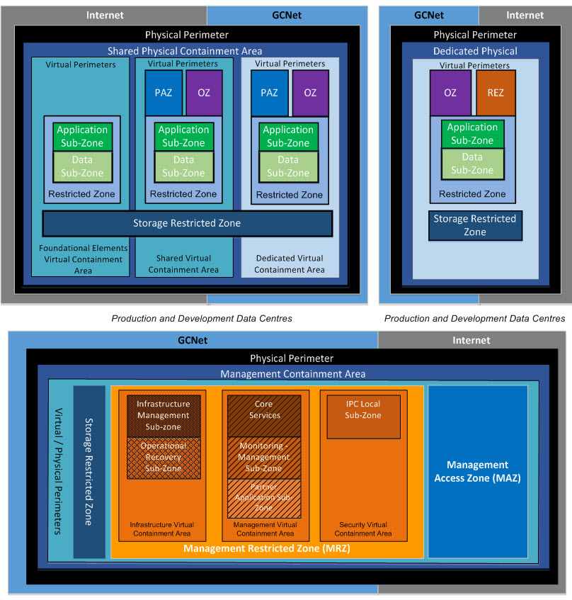
The management containment area will host workloads that administer and support the infrastructure components and partner organizations' workloads across all DCs. Unlike the other containment areas that deploy zones based on types of workloads, the zones within this containment area are based on function. All infrastructure components within the DC containment areas will have system management or out-of-band management interfaces connected to the Management Restricted Zone (MRZ). As depicted in Figure 20, the management containment area will consist of the following zones:
| Zone | Description |
|---|---|
| Management Access Zone (MAZ) | The Management Access Zone (MAZ) provides secure access to manage physical and virtual IT infrastructure components. User capabilities are based on their approved roles and responsibilities. MAZ is the only connection between users (PAZ and OZ) and the Management Restricted Zone (MRZ). MAZ could disallow access to critical management tools from PAZ. MAZ contains VDI (Virtual Desktop Infrastructure) so that specialized management tools are not deployed on physical desktops which improves security and decreases costs. |
| Management Restricted Zone (MRZ) | The Management Restricted Zone (MRZ) is a Restricted Zone for management services. MRZ contains FCAPS (Fault, Configuration, Accounting, Performance, and Security) tools. User capabilities are based on their approved roles and responsibilities. MRZ communicates with all zones (OZ, RZ, and PAZ) because MRZ manages the zones. MRZ contains the following sub-zones to segregate capabilities to improve security:
|
4.6.6 ITSG-22 and ITSG-38 in the Virtualized data Centre
ITSG-22 (Baseline Security Requirements for Network Security Zones in the Government of Canada) and ITSG-38 (Network Security Zoning) provide guidance and examples to GC departments and agencies on the implementation of network security zones. However, they do not prescribe an exact architecture, nor do they mandate the use of physical devices within Zone Interface Points (ZIPs).Footnote 5
The containment areas depicted in Figure 20 can easily be deployed with virtual switches in place of physical switches, and virtual firewalls in place of physical firewalls, while still maintaining the principles and controls identified within ITSG-22/38.
While additional risk is presented in a virtualized environment (the hypervisor is a new attack surface), this risk can be mitigated by implementing NIST and Communications Security Establishment Canada (CESG) guidance, as well as the standard process of protecting access to the hypervisor along with any other DC service.
Additional security benefits are realized through the virtualization of network devices, such as a firewall/traffic filtering policy that can now be applied to traffic directly at a server's virtual Network Interface Card (vNIC). Using legacy technologies, server traffic would arrive at a firewall only after being routed and/or switched through a network. In this network, a switch would (generally) aggregate traffic across many servers and present it to the firewall on a common interface to save on equipment costs. Within the network, servers could communicate with other servers unknown to and unstopped by the firewall. In order to prevent this traffic, the network device would need to be configured to prevent "unrequired" server-to-server communication. In other words, the network would need to apply server-specific filtering/firewall policies. Should this policy be missing, servers which should not be communicating could communicate, undetected. In comparison, within a virtualized architecture, each server is configured with its own (virtual) firewall, enabling policy enforcement in a single location. This both removes policy which is likely duplicated in the firewall and switch, and allows an auditor to review the active policy for correctness by looking in a single place. In addition to having a virtual firewall attached directly to a virtual server, other security services can also be moved off the switch, deployed right at the Network Interface Card (NIC). For example, traffic can be inspected at a higher level (e.g. application) as part of:
- network intrusion detection, and
- intrusion prevention.
In addition to services normally deployed on the server, they are now able to be deployed at the vNIC, including:
- host intrusion detection, and
- malicious code detection.
By deploying services normally run in single instances on the server via a common service run on the hypervisor, associated operational costs should decrease.
If one steps back and examines the fully converged virtual server world now available on the x86 platform, in many ways it resembles a traditional mainframe architecture – a shared CPU, memory and storage pool shared by a number of virtual machines isolated and connected to each other by a hypervisor. In fact, the term hypervisor comes from mainframe computing in the 1960s.
It is recognized that even with an improved security posture through virtualization, some applications may be better served via deployment on physical networks, firewalls and servers. However, it is also worth noting that such applications are typically not best suited for deployment within a consolidated DC infrastructure.
5. Data Centre Service Management
The intent of this section is to present a partial vision of service and systems management in Shared Services Canada's (SSC's) target state of cloud-enabled data centre (DC) services of the future. Albeit enterprise- and domain-specific service and systems management are much broader than DC consolidation, it is worthwhile describing context and expectations from a DC services perspective.
The pace of government change and its appetite for technology has increased dramatically and continues to do so. The traditional five-year business plan and lagging IT alignment is no longer acceptable. (There are limits to the approach of "do more with less.") In its place, industry has been gradually evolving towards a more agile model with shorter cycle times (e.g. on-demand), manually allocated resource pools, Blade servers, virtual machines, real-time infrastructure, self-service provisioning, automated provisioning, dynamic resource allocation and, eventually, a fully automated orchestration capability that adjusts dynamically when its monitoring indicates that live operation is failing to meet predefined orchestration policies, workload profiles and performance objectives.
These new capabilities enable dramatic improvements in innovation, development cycles, scalability, elasticity, self-service provisioning of infrastructure, less downtime, better use of existing assets and licensing, and a reduction in the IT effort and cost required to provision what traditionally would have required complex labour-intensive engineering and changes.
The following illustrates service provisioning within the target-state DC services:
- A partner organization subscribes to a DC service such as Application Hosting with an Enhanced Tiered Service Package.
- A Partner Infrastructure Lead responsible for managing the DC's cloud infrastructure (for the partner organization's application teams) is trained in the use of the DC service's cloud-based infrastructure and the overall Cloud Manager tool with its various capabilities (service portal, orchestration guidelines, self-service provisioning, monitoring and status, show-back, etc.).
- The Partner Infrastructure Lead consults with the application specialists (and a SSC DC technical liaison, if required) to define resource quotas (compute, storage, memory, network, etc.), orchestration policies, workload profiles, and other aspects of collaboration, responsibility, integration, etc.
- Based on earlier requirements from the partner organization's application expert, the Partner Infrastructure Lead uses the Cloud Manager to request the provisioning of the application hosting instances, which are then automatically identified and committed to the partner organization's Cloud Manager (the self-service provisioning request is fulfilled automatically).
- The partner organization loads its workloads onto the new application hosting instances, and initiates its testing and acceptance before releasing the application to operations and business users.
- The Partner Infrastructure Lead monitors or is alerted to workload operational performance and dynamic resource allocation to ensure the systems stay within operational limits. Orchestration, dynamic resource allocation and performance management activities are mostly automatic.
- For more critical cases, however (possibly depending on predefined criteria for more critical actions, policies and profiles), it is possible that the Partner Infrastructure Lead may be required to "OK" some actions by orchestration and dynamic resource allocation.
- The Partner Infrastructure Lead maintains communication with the application team to ensure they are apprised of workload performance and issues, and to field any new requests or changes that need to be provisioned or discussed. Note that partner organizations require their own change management, not to provision resources but, for example, to assess and decide where to use resources among competing application team demands, to schedule their provisioning as part of a larger application release, etc.
As illustrated in Figure 5: Conceptual Business and Technology Platform, several features are required for the successful implementation of this target capability.
5.1 Self-Service
Both traditional IT self-service and cloud self-service will be required by SSC partner organizations and users of DC services. Self-service in the traditional IT service context generally refers to the ability for users to access a service portal, where they can report incidents or submit requests (usually from a request catalogue), and search for answers in an FAQ or a knowledge base maintained by the Service Desk.
5.2 Service Orchestration
Orchestration provides for overall management of cloud-based infrastructure to deliver its inherent benefits, including dynamic load balancing, rapid elasticity, scalability, capacity on-demand, provisioning/deprovisioning of resources, scheduling, monitoring and tracking of virtual and physical resource performance, allocation and relationships. It performs these functions automatically and is often referred to as autonomic resource management. The overall capability is governed by orchestration policies and workload profiles or templates, as defined by DC staff and the partner organization's designated lead responsible for provisioning and managing their cloud-based services and resources.
5.3 Service Broker
The National Institute of Standards and Technology (NIST) definition of cloud broker elevates traditional on-demand provisioning to a more dynamic and customer-managed model. It achieves this by allowing services to be provisioned by other cloud providers (e.g. community and public cloud providers), and executes with an ease and speed not possible by the sourcing (brokering and coordination) of traditional IT environments. However, offering third-party delivered cloud-based services to customers still requires prior selection and integration based on DC sourcing practices, and ongoing collaboration and management.
5.4 Measured Services
Cloud management automatically controls the use and optimization of resources. It also provides monitoring, reporting and cost accounting/charging for resource usage. One or more metering models and their associated metering parameters may be offered by the service provider(s). Different models may be in play simultaneously, depending on which deployment models are in use (hybrid, demand spill-over to public cloud services, bursting, etc.).
Appendix A: Data Centre Requirements
Policy and Legislative Requirements
The following policy and legislative requirements were developed in consultation with Shared Services Canada (SSC) partner organizations and stakeholders.
| Ref | Capability | Description |
|---|---|---|
| PL-1 | Access to Data | The architecture must:
|
| PL-2 | Service Levels | The architecture must:
|
| PL-3 | Government of Canada (GC) Policy, Regulation and Legislation | The architecture must also be able to satisfy other policy requirements as defined and/or identified in Data Centre Consolidation – Summary of Requirements. |
Enterprise Requirements
The following enterprise requirements were developed in consultation with SSC partner organizations and stakeholders.
| Ref | Capability | Description |
|---|---|---|
| ER-1 | IT Service Management | The architecture must support:
|
| ER-2 | Service Delivery through Online Portal and Service Catalogue | The architecture must support the development and implementation of a service catalogue and service portfolio management function. |
| ER-3 | Service Monitoring/Reporting | The architecture must support the capability to establish standardized metrics and to measure performance against Key Performance Indicators (KPIs) to help improve service quality through monitoring and reporting |
| ER-4 | Information Lifecycle Management (ILM) | The architecture must allow partner organizations to identify the minimum data retention policies applicable for information lifecycle management, such that cost-effective storage solutions can be provisioned while ensuring enforcement of ILM policies. |
Partner Organization Requirements
The main objective of the SSC Data Centre Service is to achieve the following goals:
| Ref ID | Capability | Description |
|---|---|---|
| PR-1 | Standard Delivery | The architecture should provide a coordinated service delivery model that spans and supports departmental IT requirements. |
| PR-2 | Service On-Demand | The architecture design should provide application owners with the capability to order services, on demand, though an online service catalogue. |
| PR-3 | Security | The architecture must support a confidentiality/integrity/availability profile of Protected B/Medium/Medium (PBMM). |
| PR-4 | Lower CAPEX/OPEX | The architecture design should provide common infrastructure services that result in reduced operational and capital expenditures across the GC. |
| PR-5 | Reduced Footprint | The architecture design should reduce the GC DC footprint through consolidation and centralization. |
| PR-6 | Efficiency | The architecture design should reduce the environmental impact by leveraging DC efficiencies. |
| PR-7 | Scalability | Infrastructure must be capable of scaling (up and out) the availability of IT resources (compute, network, storage) to support graduated workload demands in order to maintain target performance metrics. |
| PR-8 | Elasticity | Infrastructure must support elastic capabilities to dynamically scale (up, down, in, out) the availability of IT resources (compute, network, storage) in response to real-time workload demands, including both anticipated and unanticipated surges and declines in I/O, compute and storage requirements, in order to achieve target performance metrics. |
| PR-9 | High Availability/Business Continuity | The infrastructure should provide high availability (99.9%) access to IT systems, applications and information (24x7x365) and provide IT service and business continuity for mission-critical applications. |
| PR-10 | Big Data Processing | The architecture must support the ability to process large volumes of data, including business intelligence, satellite imagery and digitized files. |
| PR-11 | High-Performance Computing | The architecture must support the ability for departments and agencies to conduct high-performance computing to perform scientific and research activities. |
| PR-12 | Storage | The architecture must provide access to large storage repositories to support data warehousing, business intelligence and analytical activities. |
| PR-13 | Data Access | The architecture must support the capability to enable data access to other government departments, agencies, academia, industry, stakeholders and citizens ‒ nationally or internationally. |
| PR-14 | Mobility | The architecture must provide the capability to access data and applications using mobile devices and remote access technologies. |
| PR-15 | Reporting | The architecture must provide the capability to generate financial and service-level reports to meet Treasury Board, partner organization and business reporting purposes. |
| PR-16 | Performance Monitoring | The architecture must provide performance monitoring and reporting capability on architectural elements, including platform components, application performance, user response time and custom metrics. |
Security Requirements
The following security requirements were developed in consultation with SSC partner organizations and stakeholders.
| Ref | Capability | Description |
|---|---|---|
| SR-1 | Security | The architecture must support the following security requirements:
|
Technology Requirements
The following table identifies the high-level technology requirements that have been generated through design efforts and consultations with partner organizations.
| Ref ID | Capability | Description |
|---|---|---|
| TR-1 | Multi-Tenancy | The DC will provide an environment capable of hosting multi-tenant workloads of similar and different data classifications (i.e. Protected A, Protected B). |
| TR-2 | Orchestration | The infrastructure will provide the ability for orchestrated deployment of DC services. |
| TR-3 | Security Separation | The DC will provide a flexible security architecture to maintain separation (physically and/or virtually) between partners' data that have different security profiles hosted within the DC. |
| TR-4 | Secured Environments (INTRAnet/INTERnet) |
The DC will provide secured environments to host both partner department and agency public-facing services/applications (i.e. public Internet sites), as well as intra-government-facing services/applications (i.e. GC DOCS, GCPedia, Peoplesoft, Content Sharing, VoIP/Video, etc.). |
| TR-5 | Common Services | The DC will provide secured environments to host common services/applications that can be leveraged across all client departments and agencies, as well as a restricted number of departments and agencies. |
| TR-6 | Disaster Recovery | Geographically separate DCs will provide disaster recovery services for the locally paired regional DCs. |
| TR-7 | Responsiveness | The infrastructure will provide strategic interface points within the infrastructure to capture traffic flows for performance monitoring, trending analysis, and traffic feeds into an information protection centre. |
| TR-8 | Virtualization | The architecture will utilize virtualization capabilities to enable provisioning and reduction of hardware/software resources, enable workload portability, and improve availability, service level and service quality. |
| TR-9 | Consolidation | The architecture will utilize and apply consolidation principles across the DC architecture to achieve reductions in cost, operation, administration and management of software and hardware components. Multiple workloads should be combined into a single physical server to increase utilization and reduce total cost of ownership. |
| TR-10 | Standardization | The architecture will employ standardization principles to leverage economies of scale and reduced hardware/software components, with lower operations and management costs. |
| TR-11 | Workload Mobility | The architecture must provide the ability to support workload mobility across multiple provisioning channels using open standards to avoid vendor lock-in. |
| TR-12 | Single ITSM/ESM Capability | The architecture must support a single ITSM/ESM solution that enables multi-cloud management services and the ability to perform workload mobility across a multi-vendor private, public or hybrid cloud computing infrastructure. |
Appendix B: References
The following documents form part of the reference material library that has been utilized for the creation of the Data Centre (DC) Reference Architecture Document (RAD).
| Ref ID | Details |
|---|---|
| 1 | Shared Services Canada – Integrated Business Plan |
| 2 | Shared Services Canada – Report on Plans and Priorities |
| 3 | Shared Services Canada – Final DCC Current State Report |
| 4 | Shared Services Canada ‒ DCC Objectives and Strategic Requirements |
| 5 | Shared Services Canada, Data Centre Services Target Services Data Sheets |
| 6 | Shared Services Canada, Master Functional Directives |
| 7 | Communications Security Establishment Information Technology, Security Guidance, Guide to Managing Security Risk from Information Systems, Security Control Catalogue, ITSG-33 – Overview and associated annexes. |
| 8 | Communications Security Establishment Information Technology, Security Guidance, Baseline Security Requirements for Network Security Zones in the Government of Canada, ITSG-38 |
| 9 | Communications Security Establishment Information Technology, Security Guidance, Network Security Zoning ‒ Design Considerations for Placement of Services within Zones, ITSG-22 |
| 10 | Shared Services Canada, IT Shared Services Security Domain & Zones Architecture |
| 11 | Canadian Standards Association, Privacy Code [http://www.csa.ca/cm/ca/en/privacy-code/publications/view-privacy-code]. |
| 12 | Shared Services Canada, Data Centre Consolidation Summary of Requirements |
| 13 | U.K. Government, CPA Security Characteristics for Server Virtualization |
| 14 | NIST SP 500-292: Cloud Computing Reference Architecture |
| 15 | NIST SP 800-145: The NIST Definition of Cloud Computing |
| 16 | NIST SP 800-146: Cloud Computing Synopsis and Recommendations |
| 17 | NIST SP 800-125: Guide to Security for Full Virtualization Technologies |
Appendix C: Acronyms and Abbreviations
This section contains the definition of acronyms, terms and abbreviations used within this document.
| Acronym or Term | Definition |
|---|---|
| AD | Active Directory – directory service developed by Microsoft |
| ADC | Application Delivery Controller – an application appliance, either hardware or software, that provides specialized functions to enhance the delivery of applications and content. ADCs typically include features such as WAN optimization, SSL acceleration/SSL Offloading, Single Sign On (SSO), Content Switching, Load Balancing and Web Caching capabilities. |
| ADO.NET | A set of classes that expose data access services for .NET Framework programmers |
| ALM | Application Lifecycle Management |
| App-RZ | Application Restricted Zone – network security zone for mission-critical applications |
| ASP.NET | Microsoft's Active Server Pages (ASP).NET technology is a server-side web application framework designed for web development to produce dynamic web pages. |
| AV | Anti-Virus ‒ software used to prevent, detect and remove malware |
| B2G | Business to Government |
| C2G | Citizen to Government |
| CESG | The U.K. Government's national technical authority for information assurance (IA). It protects the U.K. by providing policy and assistance on the security of communications and electronic data, in partnership with industry and academia. |
| CI | Converged Infrastructure ‒ a pre-engineered set of servers, storage, networking and security systems that are integrated into shared pools of interoperable resources, and managed through a common management and orchestration platform |
| CIFS | Common Internet File System |
| CNA | A converged network adapter is a single network interface card that contains both a Fibre Channel host bus adapter and a TCP/IP Ethernet Network Interface Card. |
| COTS | Commercial off-the-Shelf describes ready-made products that can be obtained easily. |
| CPU | Central Processing Unit |
| DB-RZ | Database Restricted Zone – network security zone for sensitive and/or critical data stores |
| DCN | Data Centre Network – the network and security infrastructure deployed within the data centre (DC) |
| DHCP | Dynamic Host Control Protocol |
| DHCP | Dynamic Host Configuration Protocol ‒ a network protocol used to configure the IP address of the devices that are connected to a network |
| DNS | Domain Name Server |
| DR | Disaster Recovery – process, policies and procedures for recovery or continuation of technology infrastructure. Refers to DC service protection that is provided out-of-region and across DCs, using replication technologies such as platform-based replication and asynchronous storage-based replication. |
| EJB | Enterprise JavaBeans is an architecture for setting up program components, written in the Java programming language, that run in the server parts of a computer network using the client/server model. |
| ESCON | Enterprise Systems Connection is a marketing name for a set of IBM and vendor products that interconnect S/390 computers with each other and with attached storage, locally attached workstations, and other devices using optical fiber technology and dynamically modifiable switches called ESCON Directors. |
| FCoE | Fibre Channel over Ethernet ‒ storage protocol that enables Fibre Channel communications to run directly over Ethernet |
| FCP | Fibre Channel Protocol |
| FICON | Fiber Connectivity ‒ a high-speed input/output (I/O) interface for mainframe computer connections to storage devices |
| G2G | Government to Government |
| GCNet | Government of Canada Network – Government of Canada inter-building network |
| GPP | General Purpose Platform – a computing and storage platform, typically based on Converged Infrastructure, used to host common workloads (e.g. J2EE, .Net, COTS Application Hosting) |
| HA | High Availability provides DC service protection within and across DCs in the same geographic region, using various techniques such as automated failover, clustering and synchronous replication at the network, platform and storage layers. |
| HBA | A Host Bus Adapter is a hardware device, such as a circuit board or integrated circuit adapter, that provides I/O processing and physical connectivity between a host system (such as a server) and a storage device. |
| HIDPS | A Host-based Intrusion Detection/Prevention System is an intrusion detection system that monitors and analyzes the internals of a computing system, as well as (in some cases) the network packets on its network interfaces. |
| HPC | High Performance Computing |
| HSM | Hierarchical Storage Management is policy based management of file backup and archiving in a way that uses storage devices economically, without the user needing to be aware of when files are being retrieved from backup storage media. |
| IaaS | Infrastructure as a Service ‒ the capability provided to the consumer to provision processing, storage, networks and other fundamental computing resources where the consumer is able to deploy and run arbitrary software, which can include operating systems and applications |
| IDE | Integrated Development Environment |
| IDPS | Intrusion Detection and Prevention System – IDS is also capable of taking some specified action automatically after detecting an attack. |
| IDS | Intrusion Detection System – system capable of detecting specified attack vectors, and zero day attack |
| Internet POP | On the Internet, a Point-of-Presence is an access point from one place to the rest of the Internet. |
| Inter-Region HA | High Availability system design, typically deployed in active-active fashion in two DCs within a small region, e.g.30 kilometers apart |
| IOPS | Input/Output Operations Per Second – performance measurement for storage |
| IP PBX | An IP PBX is a private branch exchange (telephone switching system within an enterprise) that switches calls between VoIP (Voice over Internet Protocol or IP) users on local lines, while allowing all users to share a certain number of external phone lines. |
| IPAM | Internet Protocol Address Management is a method of tracking and modifying the information associated with a network's Internet Protocol (IP) address space. |
| IPC | Information Protection Centre |
| IRC2 | Integrated Requirements Release Change and Configuration |
| iSCSI | Internet Small Computer System Interface is an IP-based storage networking standard for linking data storage facilities. |
| ITIL | Information Technology Infrastructure Library |
| ITSG | Information Technology Security Guide |
| ITSM | Information Technology Service Management |
| J2EE | Java 2 Enterprise Edition is a Java platform designed for the mainframe-scale computing typical of large enterprises. |
| J2EE | J2EE (Java 2 Platform, Enterprise Edition) is a Java platform designed for the mainframe-scale computing typical of large enterprises. |
| JDBC | A Java-based data access technology that defines how a client may access a database |
| JSP | JavaServer Pages is a technology that helps software developers create dynamically generated web pages based on HTML, XML, or other document types. |
| LAMP | Linux, Apache, MySQL, PHP is an open source web development platform that uses Linux as the operating system, Apache as the web server, MySQL as the relational database management system and PHP as the object-oriented scripting language. |
| LUNs | Logical Unit Number – number used to identify a logical unit, a device addressed by the SCSI protocol |
| NAS | Network Attached Storage – network attached file-level storage |
| NCR | The National Capital Region includes Ottawa and Gatineau. |
| NFS | A Network File System is a distributed file system protocol allowing computers to access files over a network. |
| NIC | Network Interface Card |
| NIST | National Institute of Standards and Technology |
| NTP | Network Time Protocol is a networking protocol for clock synchronization between computer systems. |
| ODBC | Open Data Base Connectivity is a standard database access method developed to make it possible to access any data from any application. |
| OPI | Office of Primary Interest |
| OS | Operating System |
| Out-of-Region DR | Disaster Recovery system design, typically deployed in active-passive fashion in two DCs separated by a large distance, e.g.1,000 kilometers apart |
| OZ | Operations Zone – a network security zone for normal GC operations, includes both user workstations and OA services such as Print and File |
| PaaS | Platform as a Service ‒ the capability provided to the consumer to deploy onto the cloud infrastructure consumer-created or acquired applications created using programming languages and tools supported by the provider |
| PAZ | Public Access Zone – a network security zone that controls traffic between a public zone and either an Operational Zone or a Restricted Zone |
| PHP | "PHP Hypertext Preprocessor," a server scripting language for creating dynamic and interactive web pages |
| PMI | Privilege Management infrastructure includes programs, processes, technologies and personnel used to create trusted digital identity representations of Individuals and Non-Person Entities (formerly referred to as Identity Credential Access Management) |
| PZ | Public Zone – a network security zone that is unsecured and outside the control of the GC. The best example of a PZ is the Internet |
| RACI | A model that is Responsible, Consulted, Accountable, Informed |
| REZ | Restricted Extranet Zone ‒ a network security zone for normal connecting with trusted partners. |
| RPO | Recovery Point Objective ‒ the maximum tolerable period of time in which data might be lost from an IT service due to a major incident. |
| RTO | Recovery Time Objective – the duration of time and a service level within which a business process must be restored after a disaster |
| RZ | Restricted Zone – a network security zone appropriate for critical applications (see App-RZ) and data (see DB-RZ), as well as for management workstations |
| SaaS | Software as a Service ‒ the capability provided to the consumer to use the provider's applications running on a cloud infrastructure |
| SAN | A storage area network is a dedicated network that provides access to consolidated, block level data storage. |
| SAN | Storage Area Network, a dedicated network providing access to block-level storage |
| SAS | Serial-Attached SCSI is a method used in accessing computer peripheral devices that employs a serial (one bit at a time) means of digital data transfer over thin cables. |
| SATA | Serial Advanced Technology Attachment is a new standard for connecting hard drives into computer systems. |
| SDE | Software Development Environment |
| SDK | Software Development Kit |
| Service Catalogue | A service catalogue may include a variety of information on services offered to partners, including description and types of services, supported SLAs, and who can view or use the services. |
| SNAP | Snapshot is a point-in-time copy of a defined collection of data |
| SPP | Special Purpose Platform – a computing and storage platform geared to particular needs that is used to host special requirements that are not well suited for the General Purpose Platform (e.g. High Performance Computing, Mainframe, VoIP Gateway Appliance) |
| SRM | Site Recovery Manager |
| SSD | A Solid-State Drive is a data storage device using integrated circuit assemblies as memory to store data persistently. |
| TCP/IP | Transmission Control Protocol/Internet Protocol |
| UAT | User Acceptance Testing |
| UPS | Universal Power Supply |
| VDI | Virtual Desktop Infrastructure |
| VM | Virtual Machine |
| VoIP | Voice over IP |
| VPN | Virtual Private Network refers to an MPLS virtual private network implemented using Virtual Routing and Forwarding (VRF) technology. |
| WAN | Wide Area Network |
| Workload Container | A workload container is the pairing of compute, network and storage infrastructure with an operating system and associated application-related data. |