
Reference method to measure releases of lead in particulate from stationary sources: chapter 3
Section 1: Sampling
- 1.1 Applicability
- 1.2 Principle
- 1.3 Apparatus
- 1.3.1 Sample Collection
- 1.3.2 Sample Recovery
- 1.4 Reagents and Materials
- 1.4.1 Sample Collection
- 1.4.2 Sample Recovery
- 1.5 Procedures
- 1.5.1 Sample Collection
- 1.5.2 Sample Recovery
1.1 Applicability
The sampling procedures specified in this Reference Method (RM) are applicable to the sampling of lead in particulate released into the ambient air from stationary sources.
Direct application of the sampling procedures may be limited by one or more of the following conditions:
- sample locations less than two stack diameters downstream or less than 0.5 stack diameter upstream of a flow disturbance;
- duct cross-sectional areas less than 0.071 m2 (113 in.2) or duct diameters less than 0.3 m (12 in.);
- supersaturated gas streams with entrained liquid droplets;
- gas stream flow rates less than 3 m/s (10 ft/s) or greater than 30 m/s (100 ft/s);
- excessively high stack gas temperature that may cause damage to the sampling equipment even with the use of a water-cooled probe;
- gas streams containing corrosive or unstable components;
- cyclonic flow patterns within the gas stream;
- rapid fluctuations in velocity, particulate loading and/or temperature of the gas stream due to uncontrollable process variations.
For compliance testing, possible modifications to allow sampling of sources exhibiting any of these characteristics may be approved in writing by the Minister of the Environment.
Sampling shall be done during the normal operating conditions of the process.
The release measurements referred to herein shall consist of at least three test runs. The release measurement result shall be the arithmetic average of the results of these test runs.
For each test run, the minimum sample volume shall be 1.7 m3. This usually corresponds to a sampling duration of 120 minutes.
1.2 Principle
Particulate matter is withdrawn isokinetically from a number of sampling or traverse points in an enclosed gas stream. The particulate sample is collected in the nozzle, probe, cyclone (see Section 1.3), and on a glass fibre filter, all maintained at a temperature of 120 ± 14 °C (248 ± 25°F) or at such other temperature as is necessary to prevent condensation. The particulate weight is determined gravimetrically after removal of uncombined water. The amount of lead or lead in combination with any other substances in the particulate sample is analyzed. Simultaneous determination of the gas stream moisture content, velocity, temperature, and molecular weight allows calculation of the lead concentration and the lead mass emission rate to be made.
Sampling isokinetically means that the linear velocity of the gas entering the sampling nozzle is equal to that of the undisturbed gas stream at the sampling point.
1.3 Apparatus
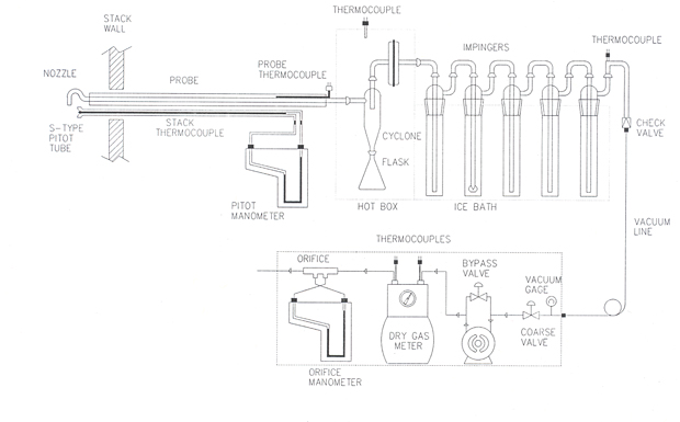
1.3.1 Sample Collection (Figure 1)
Figure 1: Lead Sampling Train

The following items are required for sample collection:
- Nozzle
- A button-hook type nozzle with sharp, tapered leading edges. The nozzle is usually made of 316 stainless steel or Incoloy 825, but quartz or other inert material may be used when high temperatures or corrosive gases are encountered. The minimum inside diameter of the nozzle shall be 4.76 mm (3/16 in.) and shall be determined using calipers.
- Probe
- A Pyrex or quartz glass liner. Where length or strength limitations preclude the use of a glass liner, a seamless tubing made from an inert and corrosion-resistant material may be used, subject to the approval of Environment Canada. The liner is encased in a stainless-steel tube with a heating and temperature indicating system capable of maintaining an exit gas temperature of 120 ± 14°C (248 ± 25°F), or such other temperature as is necessary to prevent condensation. A water-cooled probe should be used when very hot gases capable of damaging the nozzle/proble assembly are encountered.
- Pitot Tube
- An S-type (Stausscheibe) pitot tube attached to the probe. The face openings of the pitot tube and the probe nozzle shall be adjacent and parallel to each other. The configuration of the probe assembly (pitot tube, nozzle, and thermocouple) is specified in Method B of Reference Method EPS 1/RM/8 1. The probe assembly shall be calibrated according to the calibration procedures specified in Method F of Reference Method EPS 1/RM/8.
- Stack Temperature Sensor
- A calibrated thermocouple or other suitable temperature sensor capable of measuring the stack temperature to within 1.5% of the minimum absolute stack temperature. To minimize aerodynamic interaction, the pitot tube, thermocouple, and probe should be configured as specified in Method B of Reference Method EPS 1/RM/8. When high temperature gases are encountered, appropriate shielding and aspiration should be provided for the thermocouple to avoid heat radiation effects.
- Cyclone (Optional)
- A miniature Pyrex cyclone following the sampling probe and preceding the filter is to be used if a premature buildup of particulate matter on the filter medium is anticipated. The cyclone is located inside the filter compartment and is, therefore, maintained at the same temperature as the filter.
- Filter Holder
- A Pyrex filter holder with a porous, fritted glass filter support and a silicone rubber gasket. The filter support may also be made of stainless steel, Teflon, or other inert and corrosion-resistant material. The filter holder is located inside the filter compartment.
- Filter Compartment Heating System
- A heating system capable of maintaining the filter holder compartment temperature of 120 ± 14°C (248 ± 25°F) or at such other temperature as is necessary to prevent blinding of the filter due to condensation. A thermocouple or other temperature sensor is also required to measure the compartment temperature to within 3°C (5°F).
- Impingers
- Five Greenburg-Smith impingers are connected in series. The first, third, fourth, and fifth impingers are modified by replacing the tips and impaction plates of the standard design with a 13 mm (0.5 in.) ID glass tube extending to within 13 mm (0.5 in.) of the bottom of the impinger. The second impinger has the standard tip and impaction plate. The impingers are contained in an ice bath during sampling. A temperature sensor capable of measuring to within 1°C (2°F) shall be placed at the outlet of the last impinger.
- Vacuum Pump
- A leakless vacuum pump capable of maintaining an isokinetic sampling rate while continuously withdrawing a portion of the stack gases through the sampling train. The pump intake vacuum is measured to within 13 mm Hg (0.5 in Hg) by a vacuum gauge attached to the vacuum line connecting the pump to the last impinger outlet. The sample flow rate is controlled by a combination of the coarse and fine flow control valves.
- Metering System
- A calibrated dry gas meter with inlet and outlet temperature gauges, or one that is temperature-compensated. The meter and temperature gauges shall be calibrated according to the procedures specified in Method F of Reference Method EPS 1/RM/8. The temperature sensors must be capable of measuring the temperature to within 3°C (5°F).
- Orifice
- A calibrated orifice connected to the outlet of the dry gas meter. The orifice shall be calibrated according to the procedures specified in Method F of Reference Method EPS 1/RM/8.
- Differential Pressure Indicators
- The devices, such as inclined manometers, must be capable of measuring the pitot tube velocity pressure and the pressure drop across the orifice to within 0.1 mm (0.005 in.) water (H 20) on the 0 to 25 mm (0 to 1 in.) H 2O scale, and 1 mm (0.05 in.) H 2O on the 25 to 250 mm (1 to 10 in.) H 2O scale. The devices must be calibrated against a primary standard prior to the test.
- Barometer
- A barometer capable of measuring atmospheric pressure to within 2.5 mm Hg (0.1 in. Hg). The device must be calibrated against a primary standard prior to the test. Alternatively, the uncorrected atmospheric pressure provided by the local weather office may be used with an adjustment for the elevation of the sampling site.
1.3.2 Sample Recovery
The following items are required for sample recovery:
- Probe Brush
-
A nylon bristle brush of a length and diameter suitable for cleaning the probe.
- Balances
-
An analytical balance capable of measuring to within ± 0.1 mg or less and a trip or top loading balance capable of measuring to within ± 0.5 g or better.
- Miscellaneous
- Wash bottles, sufficient quantity of sample containers large enough to hold all washings and a petri dish for holding the filter sample. All items shall be made of material such as glass, Teflon, or polypropylene which are chemically inert to both the sample and the reagents used for sample recovery.
1.4 Reagents and Materials
All chemicals used shall be reagent grade. The quality of the distilled or deionized water shall conform to specifications for type III water given by ASTM2.
1.4.1 Sample Collection
The following items are required for sample collection:
- Filter
-
A flash-fired glass fibre filter (organic binder removed) of a diameter compatible with the filter holder and capable of efficiently retaining particles as small as 0.3 μm in accordance with ASTM Standard Method D 2986-71
3. The filter material must be chemically inert to stack gas components such as sulphur dioxide (S0
2). Depending on the nature of the source and the analysis required, other types of filter media may be used, subject to approval by Environment Canada. The filter must be desiccated to a constant weight before being used.
* Place the pre-weighed filter in a clean container to prevent contamination during transportation to the sampling site.
- Aqua Regia and 5% Aqua Regia Solutions
-
Aqua regia is a mixture of one volume of concentrated nitric acid to three volumes of concentrated hydrochloric acid. A 5% solution is a mixture of five volumes of the aqua regia brought up to 100 volumes with distilled or deionized water. All acids shall be of reagent grade.
- Miscellaneous
- Distilled or deionized water, crushed ice, heat-stable silicone stopcock grease, and indicating-type 6-16 mesh silica gel that has been dried at 180°C (350°F) for two hours.
* Desiccating a filter to a constant weight
Label and desiccate the filter for at least 24 hours using silica gel or equivalent at 20 ± 6°C (68 ± 10°F). Weigh the filter to the nearest 0.1 milligram at intervals of six hours or more in a room where the relative humidity is 50% or less. The weighing must be completed within two minutes after the filter is removed from the desiccator. The constant weight is attained when the difference between two consecutive readings is less than 0.5 mg.
1.4.2 Sample Recovery
The following items are required for sample recovery:
- Acetone
-
Reagent grade acetone with less than 0.001% (by weight) residue. (In non-metallic bottles).
- Water
- Distilled or deionized water.
1.5 Procedures
1.5.1 Sample Recovery
Preliminary
Select the sampling site and the minimum number of traverse points according to procedures described in Method A. In the absence of any previous knowledge of the stack variables, a preliminary test should be conducted to obtain the following data:
- velocity profile across the stack (Method B),
- stack temperature and pressure (Method B),
- stack gas molecular weight (Method C), and
- stack gas moisture content (Method D).
Methods A,B, C and D are found in Reference Method EPS 1/RM/8.
Use the data to determine the largest nozzle size possible for isokinetic sampling. Recommended minimum nozzle size is 4.76 mm (3/16 in.) I.D.
Select a total sampling time so that the sampling time per traverse point is equal to or greater than five minutes. The sample should be taken over a continuous process operating period.
Sampling Train Preparation
Prior to testing, clean the probe liner and sampling train glassware with aqua regia-and rinse several times with distilled water. Prepare the sampling train in a clean area to minimize contamination. Install the selected size nozzle on the probe. Mark the probe with heat-resistant tape to denote the location of each sampling point. Use a pair of tweezers to place the labelled and pre-weighed filter in the filter holder. Place a known volume (approximately 100 mL) of 5% aqua regia in each of the first two impingers. Place a known volume (approximately 100 mL) of distilled or deionized water in the third impinger. Leave the fourth impinger empty and place a known amount (approximately 200 g) of silica gel in the fifth. Record the volume or weight (to the nearest 0.5 mL or 0.5 g) of the content of each impinger on the Moisture Analysis Data Sheet (Figure 2).
Figure 2: Moisture Analysis Data Sheet

Set up the sampling train as shown in Figure 1. Adjust the filter compartment and probe heating systems to maintain a temperature of 120 ± 14°C (248 ± 25°F) or at such other temperature as is necessary to prevent blinding of the filter. In the presence of an acidic gas (such as S02) in the source, both temperatures shall be maintained above the acid dew point of the gas stream. Conduct a mandatory pre-test leak check of the sampling train by plugging the nozzle inlet and pulling a vacuum of 380 mm Hg (15 in Hg) for at least one minute. The leakage rate must be less than 0.57 L/min (0.02 ft3/min) or 4% of the estimated average sampling rate, whichever is less. Sampling cannot proceed until the leakage rate is acceptable. Record the actual leakage rate on the Particulate Sampling Data Sheet (Figure 3). Place crushed ice and water in the impinger box before sampling.
Figure 3: Particulate Sampling Data Sheet

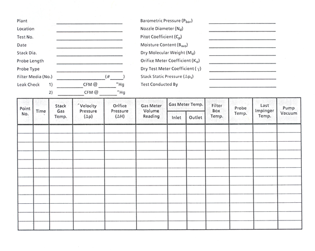
Sampling Train Operation
To begin sampling, point the nozzle directly into the gas stream at the first traverse point. Using a nomograph or a programmable calculator, determine the orifice setting for isokinetic sampling. Immediately start the vacuum pump and adjust the sampling flow rate to isokinetic conditions. Sample for at least five minutes at each traverse point, the sampling time being the same for every point. Traverse the stack cross section and maintain isokinetic sampling throughout the test. Add more ice and water to the impinger box, as required, to maintain the temperature of the last impinger exit in the range of 0° to 20°C (32° to 68°F). Record instrumentation readings on the Particulate Sampling Data Sheet (Figure 3) every five minutes, or at regular intervals that are consistent with the sampling duration established for each point, whichever is less. Readings must also be taken before and after a leak check and when sampling is halted.
When it is necessary to halt sampling temporarily either to dismantle the sampling train during port changeover or to change a train component, turn off the pump and immediately withdraw the probe from the stack. Conduct a mandatory leak check on the sampling train by plugging the nozzle, and pulling a vacuum, equal to, or greater than the maximum value observed during sampling. Record the actual leakage rate. If the leakage rate exceeds 0.57 L/min (0.02 ft3/min) or 4% of the sampling flow rate the test is invalid. If the leakage rate is acceptable, proceed with dismantling the sampling train or changing the train component. Before continuing with the test, conduct a mandatory leak check on the assembled train by following the pre-test leak check procedures used during sampling train preparation.
When the test is completed, conduct a mandatory post-test leak check on the sampling train by plugging the nozzle and pulling a vacuum, equal to, or greater than the maximum value observed during sampling. Record the actual leakage rate. For a test to be valid, the actual leakage rate must be less than 0.57 L/min (0.02 ft3/min) or 4% of the sampling flow rate, whichever is less. If the leakage rate is acceptable, proceed with recovering the samples.
1.5.2 Sample Recovery
Disconnect the probe from the sampling train. Seal all openings. Exercise care in moving the train components from the test site to the sample recovery area to minimize the loss of collected sample or the gain of extraneous particulate matter. Partition the train samples as follows:
Filter (Container No. 1)
Use a pair of clean tweezers or a sharp knife to transfer the filter and any loose material adhering to the filter support into a petri dish. Label and seal the sample container.
Nozzle, Probe Liner, Cyclone (if used), and Front-half of Filter Holder (Container No. 2)
Wash and brush the interior surfaces of the nozzle and probe with acetone. Place these washings into Container No. 2. Use acetone together with a brush or a rubber policeman to clean the inside surfaces of the cyclone (if used) and the front-half of the filter holder. Collect the acetone washings into Container No. 2. Seal and label the container and mark the liquid level.
Acetone Blank (Container No. 3)
Place a known volume (approximately equal to that in Container No. 2) of acetone, taken directly from the wash bottle being used, into Container No. 3. Seal the sample container and label it "acetone blank". Mark the liquid level.
Impingers (Container No. 4)
Measure the volume or weight (to the nearest 0.5 mL or 0.5 g) of the content of each impinger and record the results on the Moisture Analysis Data Sheet (Figure 2). If chemical analysis of the impinger liquid is required by the regulatory agency, transfer the contents of the first two impingers to Container No. 4. Rinse the inside surfaces of these impingers, all connectors, and the back-half of the filter holder with deionized or distilled water into the same sample container. Seal and label the container and mark the liquid level. Discard the contents of the third and fourth impingers. Discard the spent silica gel.