
Foam Corner Pads – Canadian Conservation Institute (CCI) Notes 20/2
Disclaimer
The information in this document is based on the current understanding of the issues presented. It does not necessarily apply in all situations, nor do any represented activities ensure complete protection as described. Although reasonable efforts have been made to ensure that the information is accurate and up to date, the publisher, Canadian Conservation Institute (CCI), does not provide any guarantee with respect to this information, nor does it assume any liability for any loss, claim or demand arising directly or indirectly from any use of or reliance upon the information. CCI does not endorse or make any representations about any products, services or materials detailed in this document or on external websites referenced in this document; these products, services or materials are, therefore, used at your own risk.
Introduction
Foam corner pads can provide excellent protection when they are properly designed. They also make very efficient use of cushioning material. This Note offers a simple table-based method of selecting corner pads for objects with cube-like shapes, according to their weight. Once a set of corner pads is constructed, they can be reused many times. Take note that the corner pad tables provided here are only to be used with polyurethane ester foam having a density of 33 kg/m³ (2 lb./ft.³) because the tables are based on cushion performance data for this material.Footnote 1
© Government of Canada, Canadian Conservation Institute. CCI 132904-0001
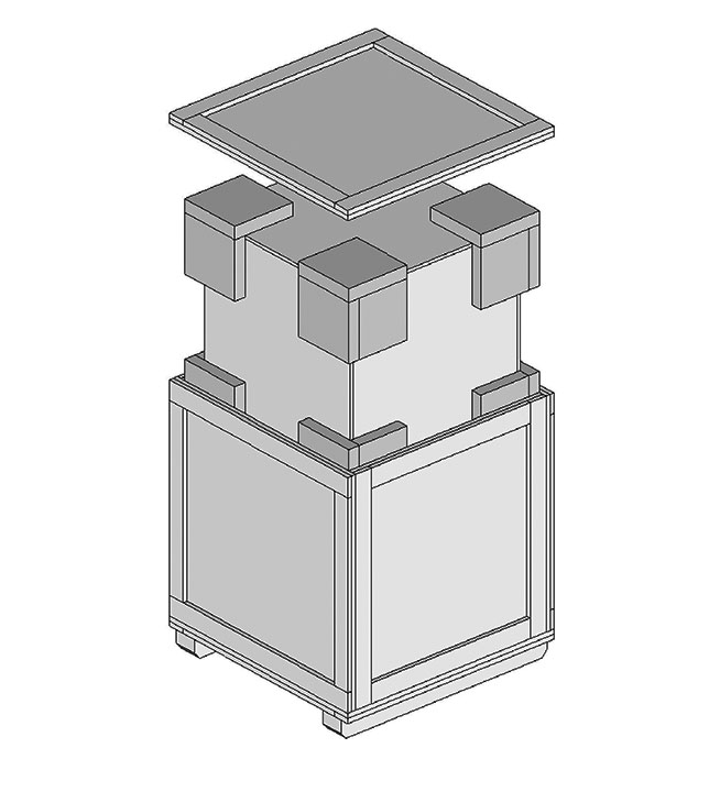
Figure 1. A double case package. The inner case floats on eight removable foam corner pads.
The cushioned object
The cushioned object can be a fragile item, an inner box or a transit structure containing one or more items. The object should be capable of sustaining moderate deceleration forces without being bent or deformed. It should also be free of loose items or parts that may move, abrade, dislodge or collide with each other.
Protective cushioning
Selection tables 6 and 7 (consult Appendix) contain information on the dimensions of corner pad parts made of polyurethane ester foam having a density of 33 kg/m³ (2 lb./ft.³). The part sizes are determined by object weight and the cushion thickness required for three categories of protection, as shown in Table 1 under the “Applications” heading. For more information on these categories, including object examples, consult Technical Bulletin 34 Features of Effective Packaging and Transport of Artwork.
| Cushion thickness | Maximum g’s | Applications |
|---|---|---|
| 51 mm (2 in.) | 50 | Delicate items |
| 76 mm (3 in.) | 40 | Very delicate items |
| 102 mm (4 in.) | 30 | Extremely fragile items |
For best results, follow these principles:
- The cushioned object should have good bending strength and be a firm assembly free of loose objects or object parts.
- The cushion system should be the most flexible part of the packaging system.
- The cushion fit should allow the package system to fit together and to be closed without excessive force. It should not bind the object in place.
- Assemble the corner pad parts securely using an adhesive such as hot-melt glue so they do not fall apart easily in service or during packing and unpacking. This is possible to achieve without excessive use of adhesive. (Ensure adequate ventilation during hot-melt adhesive use.)
Application example
An inner case measures 50 cm x 50 cm x 50 cm (20 in. x 20 in. x 20 in.). It weighs 17 kg (37 lb.) and contains several items that can sustain shocks up to 50 g’s. Construct a set of corner pads using selection tables 6 and 7.
Solution
Step 1: Select a row in the corner pad selection table that includes the inner case weight of 17 kg (37 lb.). Row 4 in Table 6 with the weight range of 5 kg to 18 kg is suitable. If working in Imperial units, the same row in Table 7 (10 to 40 lb.) can be used.
| Object weight range (kg) |
Part 1 (mm) t = all |
Part 2 (mm) t = 51 mm |
Part 2 (mm) t = 76 mm |
Part 2 (mm) t = 102 mm |
Part 3 (mm) t = 51 mm |
Part 3 (mm) t = 76 mm |
Part 3 (mm) t = 102 mm |
|---|---|---|---|---|---|---|---|
| 5 to 18 | 127 × 127 | 178 × 178 | 203 × 203 | 229 × 229 | 127 × 178 | 127 × 203 | 127 × 229 |
| Object weight range (lb.) |
Part 1 (in.) t = all |
Part 2 (in.) t = 2 in. |
Part 2 (in.) t = 3 in. |
Part 2 (in.) t = 4 in. |
Part 3 (in.) t = 2 in. |
Part 3 (in.) t = 3 in. |
Part 3 (in.) t = 4 in. |
|---|---|---|---|---|---|---|---|
| 10 to 40 | 5 × 5 | 7 × 7 | 8 × 8 | 9 × 9 | 5 × 7 | 5 × 8 | 5 × 9 |
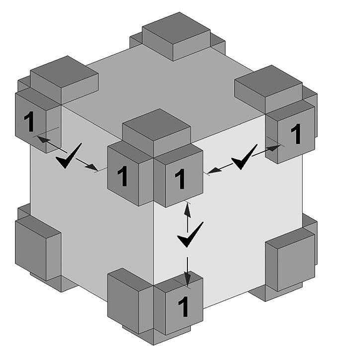
Step 2: After choosing a row that includes the inner case weight, ensure that there is room for two Part 1’s (127 mm x 127 mm [5 in. x 5 in.]) along the object height, width and depth dimensions, as shown in Figure 2.
© Government of Canada, Canadian Conservation Institute. CCI 132904-0002
Figure 2. Use Part 1 dimensions to verify that the pads will fit the object. This figure is drawn to scale and the check marks show that adequate clearance is available.
Step 3: Given that the item can sustain 50 g’s, a cushion thickness (t) of 51 mm (2 in.) (Table 1) is adequate. The dimensions of the corner pad parts can now be looked up to select Parts 2 and 3. Note that Part 1 dimensions apply to all cushion thickness values. For the dimensions of Part 2 and Part 3, look under the columns for “Part 2 (mm) t = 51 mm” / “Part 2 (in.) t = 2 in.” and “Part 3 (mm) t = 51 mm” / “Part 3 (in.) t = 2 in.” as shown in Tables 6 and 7.
| Object weight range (kg) |
Part 1 (mm) t = all |
Part 2 (mm) t = 51 mm |
Part 2 (mm) t = 76 mm |
Part 2 (mm) t = 102 mm |
Part 3 (mm) t = 51 mm |
Part 3 (mm) t = 76 mm |
Part 3 (mm) t = 102 mm |
|---|---|---|---|---|---|---|---|
| 5 to 18 | 127 × 127 | 178 × 178 | 203 × 203 | 229 × 229 | 127 × 178 | 127 × 203 | 127 × 229 |
| Object weight range (lb.) |
Part 1 (in.) t = all |
Part 2 (in.) t = 2 in. |
Part 2 (in.) t = 3 in. |
Part 2 (in.) t = 4 in. |
Part 3 (in.) t = 2 in. |
Part 3 (in.) t = 3 in. |
Part 3 (in.) t = 4 in. |
|---|---|---|---|---|---|---|---|
| 10 to 40 | 5 × 5 | 7 × 7 | 8 × 8 | 9 × 9 | 5 × 7 | 5 × 8 | 5 × 9 |
© Government of Canada, Canadian Conservation Institute. CCI 132904-0003
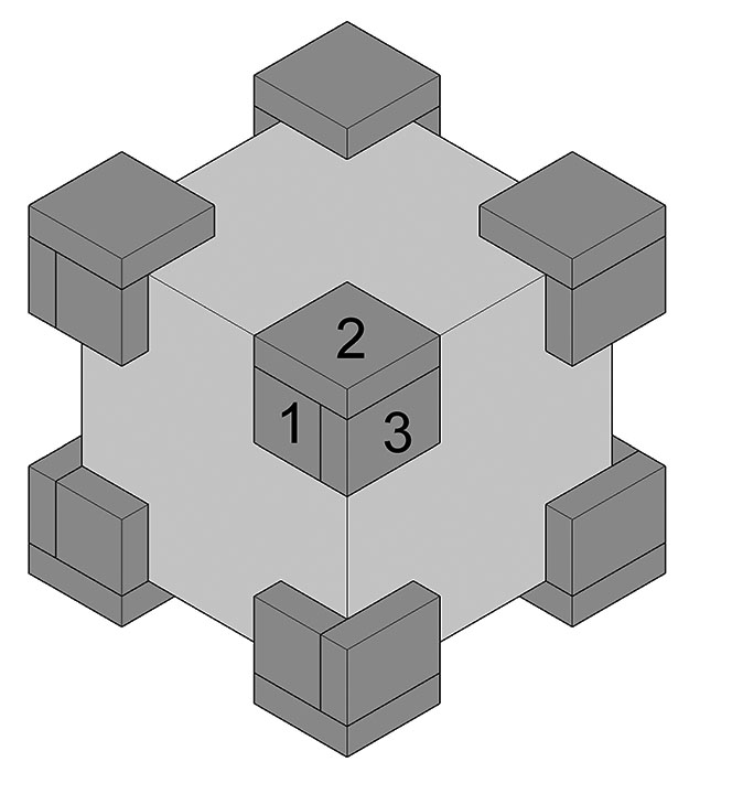
Figure 3. Foam corner pad made of Parts 1, 2 and 3.
To calculate the required inside dimensions of the shipping container, combine the object height, width and depth, then add twice the corner pad thickness to each of these dimensions.
Final comments
If the weight of the cushioned item falls inside the weight ranges of two or more rows, any of these rows can be used. This permits an adjustment of pad coverage that may offer better support or avoid clearance issues. All of the row options that include the object weight will still be within an optimum load range for polyurethane ester 33 kg/m³ (2 lb./ft.³) foam.Footnote 2
The application example begins with object weight, but it is also possible to start with corner pad size. The selected corner pad can then be checked for fit and to ensure that it is suitable for the object weight.
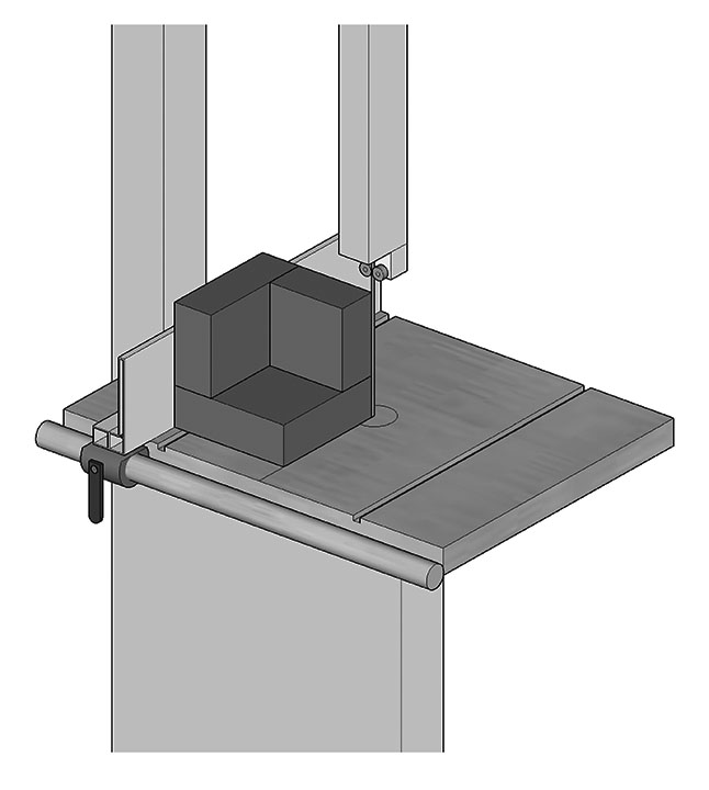
Corner pad assemblies can be squared up for a neater appearance using a band saw, carving knife or other tools (Figure 4). However, ensure that this trimming does not reduce corner pad thickness.
© Government of Canada, Canadian Conservation Institute. CCI 132904-0004
Figure 4. Trimming pad edges using a band saw.
Corner pad edges can be bevel cut for improved cushioning at low force levels and to make it easier to assemble the final package (Figure 5). The bevels can be cut at a 45° or 60° angle with a band saw or utility knife while taking care to avoid removing too much material, which could overload the reduced cushion area and lead to a loss of thickness over time and to reduced cushion effectiveness.
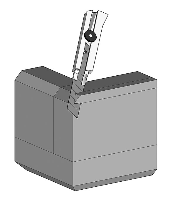
© Government of Canada, Canadian Conservation Institute. CCI 132904-0005
Figure 5. Bevelling corner pad edges using a utility knife.
Because the corner pads are removable, they can be used in multiple applications or be substituted for other sizes to accommodate different object weights. When not in use, the corner pads can be stored in the dark or in black polyethylene wrap or bags (such as garbage bags) to keep them clean and to help preserve the polyester foam material.
Appendix: Selection tables for corner pad parts
Corner pad selection tables in both metric (Table 6) and Imperial (Table 7) units of measure.
| Object weight range (kg) |
Part 1 (mm) t = all |
Part 2 (mm) t = 51 mm |
Part 2 (mm) t = 76 mm |
Part 2 (mm) t = 102 mm |
Part 3 (mm) t = 51 mm |
Part 3 (mm) t = 76 mm |
Part 3 (mm) t = 102 mm |
|---|---|---|---|---|---|---|---|
| 1 to 3 | 51 × 51 | 102 × 102 | – | – | 51 × 102 | – | – |
| 2 to 7 | 76 × 76 | 127 × 127 | 152 × 152 | – | 76 × 127 | 76 × 152 | – |
| 3 to 12 | 102 × 102 | 153 × 153 | 178 × 178 | 203 × 203 | 102 × 153 | 102 × 178 | 102 × 203 |
| 5 to 18 | 127 × 127 | 178 × 178 | 203 × 203 | 229 × 229 | 127 × 178 | 127 × 203 | 127 × 229 |
| 7 to 26 | 152 × 152 | 203 × 203 | 229 × 229 | 254 × 254 | 152 × 203 | 152 × 229 | 152 × 254 |
| 9 to 36 | 178 × 178 | 229 × 229 | 254 × 254 | 279 × 279 | 178 × 229 | 178 × 254 | 178 × 279 |
| 12 to 47 | 203 × 203 | 254 × 254 | 279 × 279 | 305 × 305 | 203 × 254 | 203 × 279 | 203 × 305 |
| 15 to 59 | 229 × 229 | 280 × 280 | 305 × 305 | 330 × 330 | 229 × 280 | 229 × 305 | 229 × 330 |
| 18 to 73 | 254 × 254 | 305 × 305 | 330 × 330 | 356 × 356 | 254 × 305 | 254 × 330 | 254 × 356 |
| 22 to 88 | 279 × 279 | 330 × 330 | 356 × 356 | 381 × 381 | 279 × 330 | 279 × 356 | 279 × 381 |
| 26 to 105 | 305 × 305 | 356 × 356 | 381 × 381 | 406 × 406 | 305 × 356 | 305 × 381 | 305 × 406 |
| 31 to 123 | 330 × 330 | 381 × 381 | 406 × 406 | 432 × 432 | 330 × 381 | 330 × 406 | 330 × 432 |
| 36 to 143 | 356 × 356 | 407 × 407 | 432 × 432 | 457 × 457 | 356 × 407 | 356 × 432 | 356 × 457 |
| 41 to 164 | 381 × 381 | 432 × 432 | 457 × 457 | 483 × 483 | 381 × 432 | 381 × 457 | 381 × 483 |
| Object weight range (lb.) |
Part 1 (in.) t = all |
Part 2 (in.) t = 2 in. |
Part 2 (in.) t = 3 in. |
Part 2 (in.) t = 4 in. |
Part 3 (in.) t = 2 in. |
Part 3 (in.) t = 3 in. |
Part 3 (in.) t = 4 in. |
|---|---|---|---|---|---|---|---|
| 2 to 6 | 2 × 2 | 4 × 4 | – | – | 2 × 4 | – | – |
| 4 to 14 | 3 × 3 | 5 × 5 | 6 × 6 | – | 3 × 5 | 3 × 6 | – |
| 6 to 26 | 4 × 4 | 6 × 6 | 7 × 7 | 8 × 8 | 4 × 6 | 4 × 7 | 4 × 8 |
| 10 to 40 | 5 × 5 | 7 × 7 | 8 × 8 | 9 × 9 | 5 × 7 | 5 × 8 | 5 × 9 |
| 14 to 58 | 6 × 6 | 8 × 8 | 9 × 9 | 10 × 10 | 6 × 8 | 6 × 9 | 6 × 10 |
| 20 to 78 | 7 × 7 | 9 × 9 | 10 × 10 | 11 × 11 | 7 × 9 | 7 × 10 | 7 × 11 |
| 26 to 102 | 8 × 8 | 10 × 10 | 11 × 11 | 12 × 12 | 8 × 10 | 8 × 11 | 8 × 12 |
| 32 to 130 | 9 × 9 | 11 × 11 | 12 × 12 | 13 × 13 | 9 × 11 | 9 × 12 | 9 × 13 |
| 40 to 160 | 10 × 10 | 12 × 12 | 13 × 13 | 14 × 14 | 10 × 12 | 10 × 13 | 10 × 14 |
| 48 to 194 | 11 × 11 | 13 × 13 | 14 × 14 | 15 × 15 | 11 × 13 | 11 × 14 | 11 × 15 |
| 58 to 230 | 12 × 12 | 14 × 14 | 15 × 15 | 16 × 16 | 12 × 14 | 12 × 15 | 12 × 16 |
| 68 to 270 | 13 × 13 | 15 × 15 | 16 × 16 | 17 × 17 | 13 × 15 | 13 × 16 | 13 × 17 |
| 78 to 314 | 14 × 14 | 16 × 16 | 17 × 17 | 18 × 18 | 14 × 16 | 14 × 17 | 14 × 18 |
| 90 to 360 | 15 × 15 | 17 × 17 | 18 × 18 | 19 × 19 | 15 × 17 | 15 × 18 | 15 × 19 |
Bibliography
U.S. Department of Defense. MIL-HDBK-304, Military Standardization Handbook: Package Cushioning Design. Washington, D.C.: U.S. Department of Defense, 1978.
U.S. Department of Defense. MIL-HDBK-304B, Military Standardization Handbook: Package Cushioning Design (With Foam Curves). Washington, D.C.: U.S. Department of Defense, 1978.
By Paul Marcon
© Government of Canada, Canadian Conservation Institute, 2021
Cat. No.: NM95-57/20-2-2021E-PDF
ISSN 1928-1455
ISBN 978-0-660-36769-9