
Features of Effective Packaging and Transport for Artwork – Technical Bulletin 34
Paul Marcon
CCI Technical Bulletins
Technical Bulletins are published at intervals by the Canadian Conservation Institute (CCI) in Ottawa as a means of disseminating information on current techniques and principles of conservation of use to curators and conservators of Canada’s cultural objects and collection care professionals worldwide. The author welcomes comments.
Abstract
This Technical Bulletin identifies shipping hazards and their effects on artwork, and it offers information on the features that make packaging effective for art shipment. The susceptibility of museum objects to shipping hazards is discussed, and control measures and design goals are provided to help the museum packer safely ship and store artwork in protective packaging. The content is based on information derived from packaging literature, CCI’s research and experimental investigations on art in transit, as well as client service work involving a wide variety of art objects.
Author
Paul Marcon received a Bachelor of Applied Science in Mechanical Engineering from the University of Ottawa. His areas of specialization in the Preservation Services Division at CCI include research into the effects of shock and vibration on museum objects; protective packaging for art in transit; moving monuments, plinths and statuary; preservation features in cultural buildings and facilities; and environmental control systems for museum buildings, display cases and object enclosures. His activities at CCI include applied conservation research, providing advice to Canadian and international museum clients, planning and oversight services for built heritage projects, and the presentation of training seminars and workshops.
Disclaimer: The information provided here is based on the current understanding of the issues presented. The guidelines given in this Technical Bulletin will not necessarily provide complete protection in all situations nor protection against every possible adverse effect caused by the packing and shipping of works of art.
Table of contents
- List of abbreviations
- Introduction
- Part 1: Shipping hazards, effects and general control strategies
- Shipping activities and hazards
- Losses in transit, on premises and off premises
- Phases of shipment
- Shipping hazard estimation and general control strategies
- Impact
- Shock
- Shock fragility ratings for objects
- Factors that influence shock fragility
- Shock and flexibility
- Shock protection for highly fragile items
- Effects of repeated shock on objects and their parts
- How to predict shock magnitude during handling
- Drop height and distribution networks
- Shock protection
- Protective cushioning
- Cushion design
- Cushion effectiveness
- Thick cushions
- General control strategies for shock
- Shock during transport
- Vibration during transport
- Compressive forces
- Puncture and blunt impact
- Temperature changes and extremes
- Humidity changes and extremes
- Humidity buffering
- Humidity buffering inside a package
- Humidity buffering and package leakage
- Unwrapped objects in a wooden shipping crate
- Wrapping, barrier materials and water vapour transmission rate
- Wrapped objects in a wooden shipping crate
- Fast-acting buffers
- Silica gel
- Precautions for wrapped objects
- General control strategies for humidity
- Water
- Pollutants
- Air pressure changes and extremes
- Pests
- General packaging guidelines
- Extreme hazards and catastrophic loss
- Part 2: Applied packaging
- Conclusion
- Acknowledgements
- Bibliography
- Endnotes
List of abbreviations
- ATA
- Air Transport Association of America
- ASTM
- American Society for Testing and Materials
- CFIA
- Canadian Food Inspection Agency
- g
- acceleration due to gravity
- g/m2
- gram per square metre
- g/sq. in.
- gram per square inch
- HTS
- handling-transportation-storage
- Hz
- Hertz
- IPPC
- International Plant Protection Convention
- ISPM
- International Standards for Phytosanitary Measures
- kg/cm2
- kilogram per square centimetre
- kg/m3
- kilogram per cubic metre
- kPa
- kilopascal
- lb./cu. ft.
- pound per cubic foot
- lb./sq. ft.
- pound per square foot
- NPPO
- national plant protection organization
- pcf
- pounds per cubic foot
- psi
- pounds per square inch
- t
- thickness
- w
- width
- WVTR
- water vapour transmission rate
Introduction
Cultural objects of all description are shipped across town, nationally and internationally on single journeys or multi-venue exhibitions. Many of these shipping prospects will raise concerns about damage or losses and may present the shipper with difficult choices about whether or not the objects should travel. When art objects do travel, they are often packaged with limited information on their damage thresholds and with little opportunity to rigorously design packages or to evaluate their performance.
The use of specialized art transport networks and overpackaging is an effective way to help address these concerns and limitations, but all shipping scenarios will involve some degree of hazard exposure, regardless of the carrier or carriers that are used. Anticipating shipping hazards and ensuring that effective protection measures are in place is both a challenge and an important responsibility for the shipper as well as the packer.
When preparing to ship artwork, the packer may wonder which materials, packaging features and procedures will deliver the greatest benefit. This is of even greater interest when time and resources are limited or when a shipping decision involves an object of exceptional importance, value or fragility.
With this in mind, the following Bulletin outlines the principles of effective packaging and shipment of artwork for the full range of shipping hazards. Part 1 identifies individual shipping hazards and their effects on artwork. It also explains how to estimate their intensity and then presents information and guidelines on how to control these effects. Part 2 shows how these principles apply to seven packaging methods that can be used alone or in combination. Part 2 also includes a general overview of shipping containers and other package-related topics.
Part 1: Shipping hazards, effects and general control strategies
Shipping activities and hazards
Shipping involves handling activities and transport in various modes, and each shipping network has its own hazard profile. The individual shipping hazards are listed and discussed in subsequent sections. Of these, shock and vibration are universal concerns, while the attention given to the remaining hazards will vary according to the type of object being shipped, when and where it travels and the shipping network that is used.
Losses in transit, on premises and off premises
Reported insurance losses offer insight into issues to consider for shipment and their relative importance. In one study of losses reported by 126 art museums, losses in transit were attributed to
- improper handling (50%),
- mysterious disappearance (34.2%),
- environmental changes (7.9%),
- theft (6.6%) and
- water damage(1.3%).Endnote 1
Note: mysterious disappearance means dissociation or the inability to locate an object or account for it. This is addressable through carrier choices, communication, project planning and documentation.
In the same study, transit represented 34.9% of all reported losses, while losses on premises and off premises were reported at 59.9% and 14.2% respectively. In each of the latter two categories, improper handling was cited as a leading cause of loss at 21.7% and 58.1%.Endnote 2
Although the focus of this Bulletin is safe shipment in packages, related activities such as packing, unpacking and in-house movement are important considerations for any shipping prospect. It is also apparent that well-made mounts and handling fixtures can offer important benefits in-house.
Phases of shipment
How does one account for all of the hazards encountered during shipment and their severity? The process begins by recognizing that every shipment has at least two handling phases and one transport phase. Handling phase activities include pickup, delivery, loading and unloading of packages on and off vehicles, and package transfers between vehicles at various points in a journey. The transport phase is the movement of cargo by road, rail, air or ocean modes.
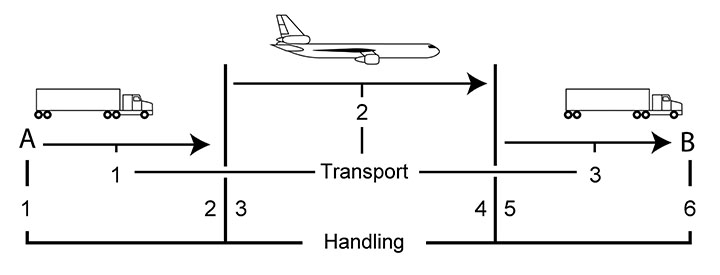
© Government of Canada, Canadian Conservation Institute. CCI 120714-0036
Figure 1. A direct door-to-door shipment has two handling phases and one transport phase; commercial shipments have many handling and transport phases. In this figure, truck transport precedes and follows air transport. The journey is made up of six handling phases and three transport phases.
Handling phase of shipment
Handling activities place significant demands on a packaging system, and most damage to commercial goods is reported to occur during this phase of shipment, as noted previously. Two important handling-related issues are
- shock caused by impacts or accidental drops of packages, and
- handling-induced loads leading to possible deformation of packaging and strain on contents.
Transport phase of shipment
The main considerations during transport are shock, vibration and environmental exposure. The shock and vibration levels in transport vehicles have been the subject of numerous investigations by commercial and military organizations because these forces cannot be observed and because packages receive full exposure to transit forces during each and every shipment. There is a very good base of knowledge on transport hazards in packaging literature, and some of this information is summarized below.
Road transport
Truck transport is frequently used for art shipment because it offers convenient source-to-destination transport and the possibility of avoiding transloading hazards between vehicles during longer journeys.
Trucks have the highest vibration levels among transport modes, but this vibration is considered to be below the damage thresholds of many commercial items. Despite this, it can still pose a risk to fragile items either directly or by secondary effects such as collision, abrasion or other interactions in or among packaged items. Unsecured packages may also fall from stacks or bounce repeatedly.
Truck vibration mainly acts in the vertical direction, and packages placed over the rear wheels or rear overhang may experience higher shock and vibration intensities than cargo in other locations. For any given vehicle type, cargo location or vehicle load, shock and vibration intensity increases with speed.
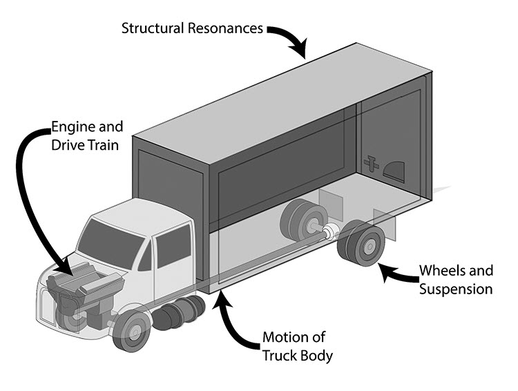
© Government of Canada, Canadian Conservation Institute. CCI 120714-0042
Figure 2.The four sources of truck vibration.
| Vibration source | Vibration frequencies | Comments |
|---|---|---|
| Structural resonances | 100 to 120 Hz | Isolated by many packaging and foam materials |
| Engine and drive train | 60 to 80 Hz | Can be isolated by some foam cushioning materials |
| Wheels and suspension | 15 to 25 Hz | Limited to minimal isolation by foam cushioning material |
| Overall motion of truck body | 3 to 6 Hz | Not isolated by most foam cushioning material |
Air ride trucks have a much smoother ride than trucks with conventional suspensions, but even the best air ride vehicle will transmit some vibration to cargo. This will be greatest for light or partial vehicle loading. New and well-maintained air ride trucks provide a better ride than old or poorly maintained ones. Carriers who own and maintain their fleets will have better control over vehicle maintenance and operators. They will also have better knowledge of vehicle operating history than those who use third-party vehicles. Reputable transport firms also enforce limits on vehicle speed (which helps avoid unnecessary force exposure) and limit driving time and thus driver fatigue, which is the leading cause of major truck accidents.
Air transport
Air transport is a popular choice for getting high-value commercial items to various destinations, and it is frequently used for art shipment. Typically, air transport subjects cargo to much less shock and vibration than travelling comparable distances in trucks or railcars. However, basic package effectiveness and the proper restraint of cargo remain important. Acceleration loads on cargo during take-off and landing are low but may cause unsecured packages to shift or fall. In flight, turbulent forces may act in all directions.
Airport equipment such as high loaders can move cargo gently on roller beds, but the tug dollies used on the tarmac may only have basic suspensions and may subject cargo to shock and vibration, especially when this equipment is operated at excessive speeds over rough surfaces. It may be difficult or impossible to supervise cargo movement at airports without having tarmac privileges.
The low hazard intensity of air transport is appealing, and the packer may be tempted to use lighter, less durable packaging to reduce its high cost. This benefit needs to be carefully considered, as significant hazards may still be encountered on other legs of the journey, such as truck transport to and from the airport (consult the section Lightweight crating precautions for additional information). Durable crates may still be necessary to ensure adequate protection during these parts of shipment (consult the section Wooden crates).
Rail transport
Rail transport is well-suited for efficient movement of bulk cargo but has been typically regarded as a hazardous mode for fragile items. Shock along the length of the train caused by slack in railcar couplings is a source of significant compressive force. Rail transport may also generate more lateral impact and vibration than other modes due to railcar movement (or hunting) from side to side within the rails. In order to reduce the risk to cargo, it is common practice to restrain its movement in railcars by filling voids between packages, using efficient box stacking patterns and other measures to immobilize loose or unstable items.
Modern rail equipment has undergone significant improvements, because it is now used to move container loads of fragile freight. Although rail transport is not a commonly used mode for the shipment of art, new equipment may increase interest in its use for some items or exhibit material in the future. Advantages of rail transport include the ability to bypass road traffic congestion and lower fuel consumption.
Ocean transport
Ocean freight is an option for large, heavy items that may be either impractical or too expensive to ship as air freight. In the past, cargo items were individually loaded onto ships using winches and cranes, and the items were manually placed in the cargo hold. Loading a single ship could take up to two weeks. Marine shipment was transformed with the onset of containerization in the late 1950s. Goods of all types are now shipped in intermodal containers. Although containers eliminate the need to handle individual cargo items, the containers will be lifted many times between their point of origin and their destination, and any unsecured contents inside the container may shift during these activities. As a result, individual package handling activities and associated hazards are reduced, but the shifting of inadequately secured container loads can lead to large damage claims.
Despite interlocking hardware and cross-bracing provisions for containers on deck, there are still accounts of containers being lost overboard in rough seas. Below deck locations may be arranged with the help of a freight forwarder.
Fragile cargo shipped by ocean needs protection from significant environmental hazards. Cargo location below deck can help reduce environmental exposure, and containers may also be fitted with insulation, heating and cooling or dehumidification systems installed internally or externally and powered by on-board or other energy sources. Large desiccant packs are also used in commercial cargo containers to help keep the contents dry.
Ocean transport is regarded as “the toughest leg” of any journey. The passages are long, lasting anywhere from 9 to 14 days, and may cover distances of 5600 to 9600 km (3480 to 5965 mi.). Container handling operations and harsh environmental conditions over the course of these journeys place severe demands on containers and freight. A complete source-to-destination journey with intermediate cargo transfers and transport may last 30 to 45 days, and containers may undergo 12 or more physical movements.Endnote 3 Despite this, commercial goods of all description travel by ocean every day. The hazard severity of ocean shipment does not exclude it as an alternative for some items as long as its hazards are well understood and accounted for in both planning and packaging treatment.
Shipping hazard estimation and general control strategies
Packaging bridges the gap between object damage thresholds and shipping hazard intensity. The complete list of hazards the art packer will need to be aware of is as follows:
- impact
- shock
- vibration during transport
- compressive forces
- puncture and blunt impact
- air pressure changes and extremes
- temperature changes and extremes
- humidity changes and extremes
- pollutants
- water
- pests (biological agents)
Some hazards will be applicable to almost all objects, and others may require more or less attention, depending on the type of objects being shipped. For hazards such as direct impact, abrasion, pests or water, the package design goal is exclusion. For shock, vibration and environmental changes, the design goal is a safe limit. The lack of detailed information on the susceptibility of artwork to some hazards can make it difficult to establish design requirements precisely, but reasonable performance goals and general control measures can be established, and these can often provide a high assurance of safety.
Impact
Impact may occur during the handling or transport phases of shipment. Impact can be the result of
- a collision between an object and a hard surface (such as the crate’s interior),
- a collision between packed objects,
- a collision between object parts,
- a collision between objects and package components,
- a collision between packages and
- dropping a package onto a hard surface.
Impact effects on objects can include scratches, dents, tears, abrasion and crack or flaw formation at the impact site. It can cause pre-existing cracks or flaws to progress and may also result in the loss of loose or damaged material.
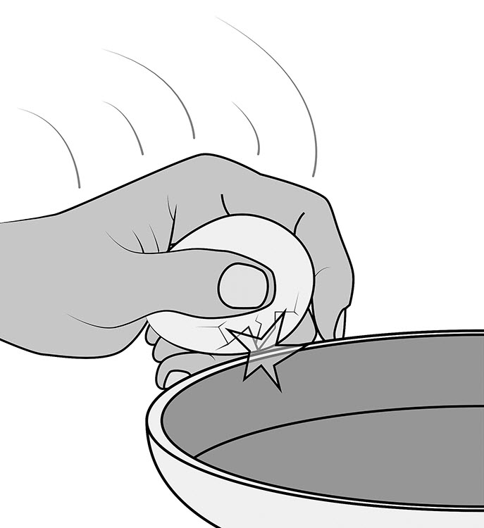
© Government of Canada, Canadian Conservation Institute. CCI 120714-0049
Figure 3. Cracking an egg by striking it on a hard-edged container. Impact against a hard edge damages the egg’s durable shell structure.
General control strategies for impact
- Use primary packaging (light, superficial packaging treatment directly adjacent to the object) to support delicate items and surfaces and to avoid impact between objects.
- Anticipate and avoid the possibility of collision in and among package components.
- Use durable partitions and restraint in containers containing multiple, heavy items.
- Ensure proper restraint of objects or packages in transport vehicles.
- Select careful handlers and drivers.
- Select carriers with well-maintained fleets.
- Provide oversight or clear instructions for parties that undertake shipping-related activities such as unpacking, in-house transport and installation.
- Inform carriers when items of unusual importance or fragility are shipped.
Shock
Damaging shock usually occurs during the handling phase of shipment. Shock damage may also occur during transport if items that have not been properly secured fall from high stacks or bounce repeatedly. The main difference between impact and shock is that shock involves a greater amount of energy that can induce significant deformation and strain in the affected item. This high energy can result from
- drops,
- forceful impact and
- collision between packages.
The effects of shock may range from non-destructive movement to the initiation and progression of damage through to severe breakage by a single shock event.

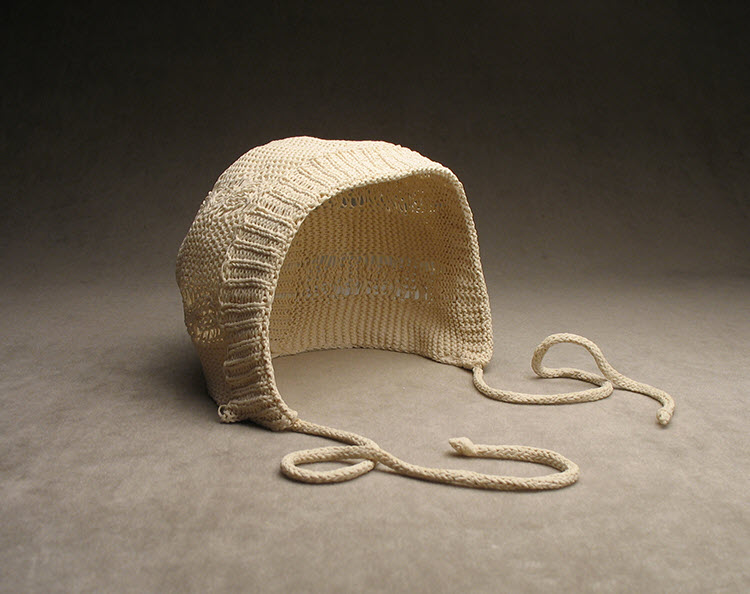
© Government of Canada, Canadian Conservation Institute. CCI 120714-0055
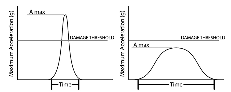
Figure 4. A bell provides an example of shock due to impact. When forcefully struck by the clapper, the entire bell structure responds as it dissipates energy supplied by the clapper impact.
The most familiar quantity used to describe shock magnitude is the g unit of acceleration. This can be thought of as a multiple of the object’s weight. For example, a shock of 100 g’s will subject an object to a force that is equal to 100 times its weight for a brief interval of time.
Many art objects and everyday items will experience significant damage when shocks reach 100 g’s or more (consult the next subsection). This shock level can occur from a free-fall drop of only a few centimetres onto a hard surface. Shock level predictions for a variety of drop heights and basic packaging treatments appear in Table 6.
Shock fragility ratings for objects
Shock fragility ratings are also expressed in g units. These are the values in g’s that should not be exceeded if damage is to be avoided. Examples of fragility ratings for commercial products and some common items are shown in Table 2. Art object examples appear in Table 3. Note that while both impact and shock can be expressed in g’s, impact and shock events of the same g value may not have comparable damage potential. If the impact event is of very short duration, it may not contain enough energy to cause an object’s structure to respond, but it may still cause local damage at the point of application.
| Category description | Common object examples |
|---|---|
| Extremely fragile 15 to 25 g |
|
| Very delicate 25 to 40 g |
|
| Delicate 40 to 60 g |
|
| Moderately delicate 60 to 85 g |
|
| Moderately rugged 85 to 115 g |
|
| Rugged 115 g and up |
|
Note: The fragility ratings in Table 2 will vary among actual objects with similar descriptions (consult the section Factors that influence shock fragility).
Fragility estimates for medium-sized canvas paintings have been obtained from simple tests using foam-cushioning material to condition shock pulses. The test procedure looked for visible damage such as losses, new crack development and the propagation of existing cracks. The results were compared with computer model predictions and were found to be in general agreement.Endnote 4 Additional studies are necessary to cover the wide range of practically encountered painting types and sizes and to more accurately identify the onset of damage, but experiments such as those described above using highly vulnerable coatings offer useful guidance.
Results of these tests show that measures to limit the deformation or “scissoring” movement of stretcher bars provide up to a twofold increase in canvas painting durability. Protective wrapping, durable frames, handling-transportation-storage (HTS) frames, backing boards and stretcher linings can all reinforce the canvas support structure. Most of these measures will also limit out-of-plane canvas displacement by enclosing the air space behind the canvas, which creates a stiffening effect that reduces canvas deflection.Endnote 5
Panel paintings can be highly susceptible to shock, especially as painting size and mass increase and when this increased mass includes deteriorated or fractured material. The damage thresholds for medium to large panel paintings that are deteriorated may be difficult to establish. Calculation-based estimates for new pine and oak panels of various sizes are summarized in Table 3.Endnote 6
Damage thresholds for fragile, unfired clay items in Table 3 are derived from drop tests of many small to medium-sized objects in a multitude of shapes. Glassware values were obtained from the literature, and the fragility of the marble sculpture element in Table 3 is derived from calculation, material properties and material condition.
In the absence of fragility ratings, estimates can be made by comparison to objects of known fragility, experience-based judgement, calculations and computer simulation. In practice, fragile items in good condition that were considered suitable for shipment have been safely shipped, through controlled networks, with cushioning that limited shock to 45 g’s or better for typical drop hazards in medium-sized (weighing 15 kg [33 lb.] or more) or larger packages. Designs that limit shock to the 25 to 40 g range for typical drop heights have been used to safely ship highly fragile contemporary art items through a variety of distribution networks.
| Category description | Museum object examples |
|---|---|
| Extremely fragile 15 to 25 g |
|
| Very delicate 25 to 40 g |
|
| Delicate 40 to 60 g |
|
| Moderately delicate 60 to 85 g |
|
| Moderately rugged 85 to 115 g |
|
| Rugged 115 g and up |
|
Notes:
- Canvas 1: Poorly adhered, damaged, flaking and brittle gesso layer (93% pigment volume concentration) on commercially prepared 60 cm x 60 cm acrylic canvas.
- Canvas 2: 64 cm x 76 cm sized linen with five coats of brittle gesso (93% pigment volume concentration).
- Pine and oak panels calculated values for panel fracture (w = width perpendicular to grain; t = panel thickness) from Richard and Mecklenburg (1991).
Factors that influence shock fragility
Given that shock damage thresholds for most objects are unknown, some of the factors that influence shock susceptibility are listed below. They include:
- material weakness
- mass (shock-induced force increases with increasing mass)
- mass and material weakness combined
- defects, flaws, pre-existing damage
- brittleness (due to material properties, environmental effects or the rate of load application)
- assembly features with a visible or hidden vulnerability
- structures or assemblies that are weak or damaged
- shape, high mass projections
- flexibility, looseness and vibration tendencies
- parts that may dislodge and cause damage
- direction of the applied shock (for example, a hollow pot or vase is more susceptible to shock applied perpendicular to the open end)
Lightweight paint particles or similar material may resist being dislodged by shock with even light adhesion force holding them in place. Note that this would not apply to loose clumps of freshly applied pastel that are light but which have a high mass relative to a very limited adhesion force. The structure that supports lightweight, loosely held or weak surface features is also a factor. If the underlying structure is responsive, such as a drum mount or canvas support as seen in older pastels, it may affect a light, weakly adhered surface layer.
Wherever material weakness and mass combine, force susceptibility will increase. Greenware (hollow, slip-moulded clay) is an excellent example of this combination; hollow slip cast items are highly susceptible to both shock and handling forces. Another example of this combination is a large panel painting with a deteriorated wood support.

Materials such as glass and ceramics have low fracture toughness and can fail catastrophically when subjected to force. The presence of a minute crack or flaw invisible to the eye may concentrate forces leading to damage progression and breakage. Primary packing features that avoid bending strain or point loads on these items can improve their durability for handling and shipment. Materials with good fracture toughness may exhibit brittle material behaviour due to the stiffening effect of rapid shock loading or low temperature.
Environmental changes can also influence object fragility. A drop in humidity can increase canvas tension and may induce strain in painting materials. Hide drum heads and stringed musical instruments may be similarly affected.
For any given material, fragility will vary with shape. The strongest shape is a sphere, and one of the weakest is a long, thin band.
Conservation treatment to improve object durability can be an asset for transport, but this may increase object susceptibility to other agents, such as future environmental changes, due to a loss of sites for movement and stress release.
Shock and flexibility
Shock effects may be amplified in flexible objects or their parts. The plot in Figure 6 is based on shock response theory for simple mechanical systems.Endnote 7 It shows the extent to which shock may be amplified in flexible parts of a cushioned item. However, it also shows that if the cushioned item is firm relative to the cushions, its response tends to unity (or 1) and will be no greater than the applied shock, which is of practical interest. While it may not be possible to measure quantities that allow response evaluations in museum practice, the theory illustrates the advantage of practical measures such as advice to float firm assemblies on softer cushions (consult the section Shock protection for highly fragile items).
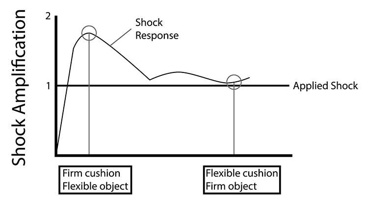
© Government of Canada, Canadian Conservation Institute. CCI 120714-0056
Figure 6. Shock response of a flexible component. Shock may be amplified in flexible elements supported on cushions, but this effect is limited if the elements are stiffer than the cushioning system.
Shock protection for highly fragile items
The foregoing offers guidance for some items that present unusual challenges due to extreme fragility, a highly fragile surface, delicate projections or pre-existing damage. If these items must travel, consider the following:
- Avoid conditions that may lead to secondary damage effects (consult the section Package dynamics).
- Support the object evenly and avoid packing methods that may induce bending or deformation.
- Ensure that the “object” to be cushioned (whether it is an object, an object on a mount or multiple items in a container) acts as a single firm unit, free of excessive flexibility or looseness.
- Float the object on soft cushions that are properly designed for the application.
- If the object is very light, the added mass of mounts, an inner case or other primary packaging can improve cushioning effectiveness.
Following the above points will create a condition in which the cushioned item moves on protective cushioning as a single firm unit, as shock and vibration energy is dissipated without any force-multiplying effects or relative movement in or among the components of the cushioned item. One practical example of this approach is the double case system.
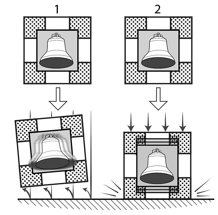
© Government of Canada, Canadian Conservation Institute. CCI 120714-0058
Figure 7. Impact energy supplied by dropping a package has to go somewhere. With proper cushioning (right image), the object does not “ring” and there is little or no package bounce after impact—energy is dissipated by oscillation of the object as a whole on its cushioning.
Effects of repeated shock on objects and their parts
Repeated exposure to shocks below single-event damage thresholds can lead to damage by fatigue (Figure 17). Fatigue theory states that damage typically occurs at about 25 to 50% of the strain that causes breakage in a single event. Art shipment investigations using shock loggers often report few or even no shock events experienced by the packaged object, even with low detector thresholds near 5 g’s (consult the section Drop height and distribution networks). This indicates that the combination of good packaging and quality transport can even be effective for avoiding fatigue effects in vulnerable items. While this simplification may apply to many scenarios, items of concern are best evaluated on a case-by-case basis.
How to predict shock magnitude during handling
The shocks that packages may receive during handling operations can be predicted using package size or weight because these attributes determine how the packages will be handled and the height from which they may be accidentally dropped. The probable drop heights in Table 4 are typical values that are based on a long history of observations, experience and investigations in the packaging field. Expressing shock hazard intensity as a drop height is convenient because it enables a cushioning requirement to be both defined and met by materials whose performance data is published for the same or similar drop height values. Note that drop hazards for mechanical handling of large packages do not normally involve a free-fall drop of the complete package as such; the drop heights will represent the height from which a raised corner or edge of a large package is dropped (Figure 8).
| Package weight | Probable drop | Form of drop | Type of handling |
|---|---|---|---|
| 0–5 kg (0–10 lb.) | 122 cm (48 in.) | Any side or corner | One-person throw |
| 5–9 kg (11–20 lb.) | 107 cm (42 in.) | Any side or corner | One-person throw |
| 9–23 kg (20–50 lb.) | 91 cm (36 in.) | Any side or corner | One-person carry |
| 23–45 kg (50–100 lb.) | 76 cm (30 in.) | Any side or corner | Two-person carry |
| 45–113 kg (100–250 lb.) | 61 cm (24 in.) | Rotating, either end roll or tip | Two-person carry/mechanical |
| 113–227 kg (250–500 lb.) | 46 cm (18 in.) | Rotating, either end roll or tip | Mechanical |
| 227+ kg (500+ lb.) | 30 cm (12 in.) | Rotating, either end roll or tip | Mechanical |
The following generalizations on drop hazards are useful for planning and design purposes:Endnote 8
- The heavier the package, the lower the drop height.
- The larger the package, the lower the drop height.
- Probable drop heights are reasonable worst-case estimates. There is no guarantee that probable drop heights will be reached, and if drops do occur, probable drop heights are unlikely to be exceeded.
- Most medium- to large-sized packages will be dropped on their bases and base edges.
- Base drops account for over 50% of the total number of drops.
- The likelihood of impacts to the upper corners or edges of a package decreases with increasing package size.
When planning, packaging for small to medium-sized items will need to be designed in anticipation of free-fall drops onto all of their sides, edges or corners. Items in large packages, on the other hand, will need to withstand rotational edge, rotational corner and rotational flat drops. Items in tall narrow crates may also be subject to topple hazards (Figure 8).
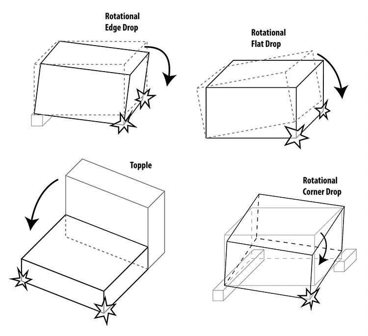
© Government of Canada, Canadian Conservation Institute. CCI 120714-0059
Figure 8. Typical hazards for large shipping cases, crates or unit loads that are handled by several persons or by mechanical equipment such as pump trucks and forklifts.
Drop height and distribution networks
The distribution network is the carrier or series of carriers that gets your package from point A to point B. Carrier choices can have a significant effect on drop hazards—the hazards may be near typical estimates shown in Table 4, higher than typical or much lower and less frequent. Small parcel networks (parcel post and express delivery services) have the most severe hazard profiles. A study of a 6.8 kg (15 lb.) package measuring 0.38 m x 0.34 m x 0.34 m (1.25 ft. x 1 ft. x 1 ft.) in the small parcel network recorded maximum drops in the range of 180 cm (71 in.).Endnote 9 A claims agent for one small parcel delivery company has stated that “all boxes should be capable of being dropped from a height of 3 m (6 ft.) without damaging contents.” Data for a 45 kg (100 lb.) package shipped as checked baggage on 34 commercial flights in Figure 9 recorded two drops in the range of 76 to 90 cm (30 to 36 in.); it validates the probable drop estimates in Table 4 and the generalizations below the table for undefined or common shipping networks.
CCI investigations of specially controlled (art handler) networks with medium- to large-sized packages containing data-loggers recorded either very few or, often, no impact events altogether, even with a detection threshold as low as 5 g’s of acceleration. These test packages were typically designed for the drop heights shown in Table 4 with cushion material designed to limit shock to approximately 45 g’s or better.
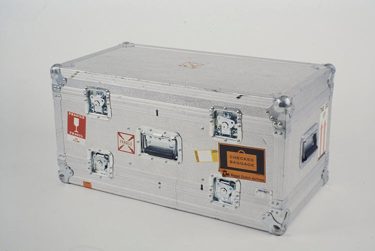
© Government of Canada, Canadian Conservation Institute. CCI 120714-0061
Figure 9. A 45 kg (100 lb.) road case measuring 43 cm x 43 cm x 71 cm (17 in. x 17 in. x 28 in.) was shipped as checked baggage on 34 commercial flights.
| Commercial airlines drop height | Number of drops |
|---|---|
| 0–15 cm (0–6 in.) | 799 |
| 15–30 cm (6–12 in.) | 27 |
| 30–46 cm (12–18 in.) | 14 |
| 46–60 cm (18–24 in.) | 1 |
| 60–76 cm (24–30 in.) | 1 |
| 76–91 cm (30–36 in.) | 1 |
Note: This table agrees with the probable drop heights in Table 4 and some of the generalizations below it for a common, high-hazard distribution network.
Shock protection
Packaging artwork often begins with primary packaging treatment such as wrapping, a mount, a support or a handling fixture. This practice is key to helping address some of the uncertainty about artwork durability, and it can provide important benefits:
- It helps direct impact to more durable parts of the object.
- It can help distribute shock forces across a broader area of the object.
- It can help reduce the susceptibility of items to shock and bending (brittle items susceptible to bending can be offered continuous support).
- It can be used to avoid secondary damage effects, such as that from a collision or abrasion.
- It can make odd-shaped items or items with fragile details easier to protect with simple cushion shapes that are easy to design and fabricate.
Primary packaging treatment provides shock protection, but the extent of that protection is not easy to quantify and it may not be consistent in all directions. Table 6 provides basic indications of shock protection offered by several primary packing treatments. This treatment alone may enable the safe shipment of some items. However, in most cases, primary packaging will form a foundation for further packaging treatment, especially when shipping highly fragile or valuable items over longer distances and to multiple venues.
| Drop height |
Metal container |
Wooden box |
Carton | 25 mm (1 in.) cushioning |
76 mm (3 in.) cushioning |
|---|---|---|---|---|---|
| 183 cm (72 in.) |
480 * | 240 * | 160 * | 120 * | 64 * |
| 122 cm (48 in.) |
392 * | 196 * | 131 * | 98 * | 52 |
| 107 cm (42 in.) |
367 * | 183 * | 122 * | 92 * | 49 |
| 91 cm (36 in.) |
339 * | 170 * | 113 * | 85 * | 45 |
| 76 cm (30 in.) |
310 * | 155 * | 103 * | 77 * | 41 |
| 61 cm (24 in.) |
277 * | 139 * | 92 * | 69 * | 37 |
| 46 cm (18 in.) |
240 * | 120 * | 80 * | 60 * | 32 |
| 30 cm (12 in.) |
196 * | 98 * | 65 * | 49 | 26 |
| 15 cm (6 in.) |
139 * | 69 * | 46 | 35 | 18 |
Note: Values followed by an asterisk (*) indicate possible damage to moderately delicate to delicate objects. Note the large improvement gained by increasing cushion thickness from 25 mm (1 in.) to 76 mm (3 in.). Protective cushions 50 mm (2 in.) thick can be effective in many practical applications if designed with the help of cushion performance data and design methods.
When using cushioning materials for supports, primary packaging and light shock protection, maximum load specifications will help avoid looseness or instability that may result from gradual material deformation under excessive load. Table 7 lists maximum loads for several commonly used materials.
| Material | Product examples | Maximum load |
|---|---|---|
| Polyurethane ether 24 kg/m3 (1.5 pcf) | NA | 0.07 kg/cm2 (1.0 psi) |
| Polyurethane ester 33 kg/m3 (2.0 pcf) | NA | 0.14 kg/cm2 (2.0 psi) |
| Polyethylene 33 kg/m3 (2.0–2.2 pcf) | Ethafoam 220 PolyPlank LAM220 PolyPlank EXT220 Plastazote LD33 |
0.18 kg/cm2 (2.5 psi) |
| Polyethylene 64 kg/m3 (4.0 pcf) | Ethafoam HS 45 PolyPlank EXT400 |
0.35 kg/cm2 (5.0 psi) |
| Polyethylene 96 kg/m3 (6.0 pcf) | Ethafoam HS 600 PolyPlank EXT600 |
0.70 kg/cm2 (10 psi) |
| Polystyrene (insulation) | Styrofoam Blue Insulation | 1.76 kg/cm2 (25 psi) |
| Polystyrene (high load) | Styrofoam Highload 40 Styrofoam Highload 60 Styrofoam Highload 100 |
2.8 kg/cm2 (40 psi) 4.2 kg/cm2 (60 psi) 7.0 kg/cm2 (100 psi) |
Note: Static load can be calculated by S = W/A, where W = object weight in kg (lb.) and A= area in cm2 (in.2).
Protective cushioning
When additional protection is required for a fragile object, protective cushioning can be designed accordingly. The most basic requirement of effective cushioning is adequate thickness, which can be calculated using the equation below. The total cushion thickness is the sum of the deflection requirement for limiting shock (2h/g) plus added thickness to avoid bottoming, which can be estimated by dividing the deflection requirement by the optimum strain, s.
The optimum strain is the amount that a cushion can deflect before it begins to bottom out. Optimum strain values for polyurethane foam, polyethylene foam and polystyrene are 70%, 50% and 30% respectively.Endnote 11 This explains why a given thickness of polyurethane foam cushioning can offer more protection than the same thickness of other commonly used materials—it can deflect as much as 70% before its performance is degraded by the bottoming effect (Table 8). In the absence of optimum strain data, a final thickness of double the deflection requirement can be used.
t = (2h/g)/s
Where:
t = total cushion thickness requirement in cm (or in.)
h = drop height in cm (or in.)
g = the required deceleration level (g's)
s = optimum strain (decimal value; for example, use 0.5 for 50%)
© Government of Canada, Canadian Conservation Institute. CCI 120714-0019
Figure 10. Protective cushioning exchanges maximum shock acceleration for shock duration by giving an object more time to slow down as it deflects into the cushioning during an impact or drop.
| Cushioning material | Optimum strain (s) % | Drop height of 46 cm (18 in.) | Drop height of 76 cm (30 in.) | Drop height of 122 cm (48 in.) |
|---|---|---|---|---|
| Polyurethane ester foam | 70 | 2.9 cm (1.1 in.) |
4.8 cm (1.9 in.) |
7.7 cm (3.0 in.) |
| Polyethylene foam | 50 | 4.1 cm (1.6 in.) |
6.8 cm (2.7 in.) |
10.8 cm (4.3 in.) |
| Polystyrene foam | 30 | 6.8 cm (2.7 in.) |
11.3 cm (4.4 in.) |
18.1 cm (7.1 in.) |
Cushion design
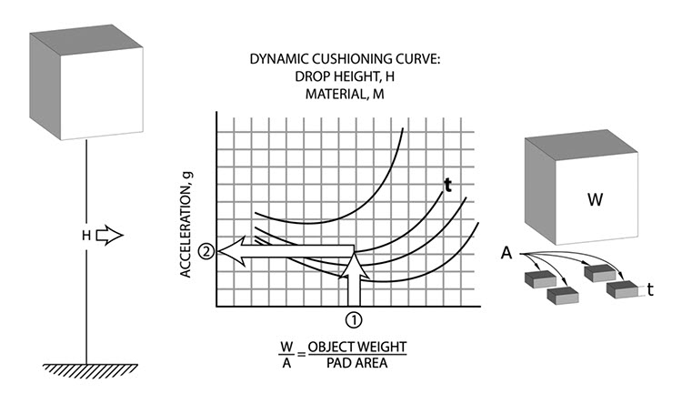
Commercial package cushioning is designed with the help of performance data published by foam material manufacturers and other sources in the form of dynamic cushioning curves. These curves are derived from tests on actual cushion material samples performed within their recommended load range.Endnote 12 Restricting loads to values under the curves helps ensure the correct use of a material and a predictable amount of protection. Military Standardization Handbook: Package Cushioning Design contains an extensive collection of cushioning curves for most commonly available materials. The procedure for using dynamic cushioning curves is summarized in Figure 11.
© Government of Canada, Canadian Conservation Institute. CCI 120714-0021
Figure 11. Summary of the cushion design method and cushioning curves used for commercial cushion design, which can be applied to museum cushioning requirements.
© Government of Canada, Canadian Conservation Institute. CCI 120714-0015
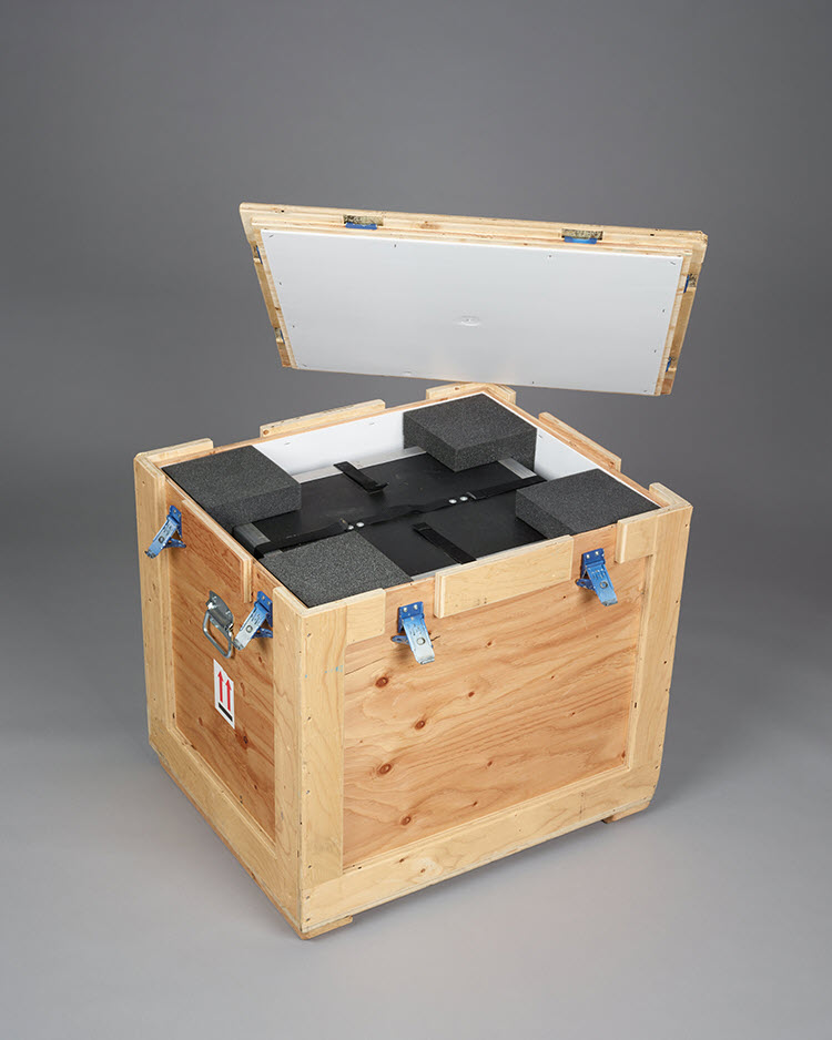
Figure 12. Double case package used during CCI protective packaging workshops. With the help of cushion design information, the reusable corner pads maximize protection while minimizing material use and package size. They are 50 mm (2 in.) thick and, with good primary packing, have protected some fragile clay test items from free-fall drops of 76 cm (30 in.) and higher.
For the double case package shown in Figure 12, the inner box weight (W) is approximately 14 kg (30 lb.) and the total pad coverage (A) on each side of the inner case is 645 cm2 (100 sq. in.). Static load is W/A = 0.02 kg/cm2 (0.3 lb./sq. in.). For a drop height of 76 cm (30 in.), applying the procedure summarized in Figure 11 for polyurethane ester foam of 33 kg/m3 (2.0 lb./cu. ft.) density predicts that a 50 mm (2 in.) cushion thickness can limit shock to 45 g’s.
© Government of Canada, Canadian Conservation Institute. CCI 120714-0023
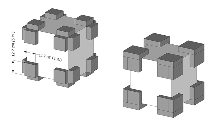
Figure 13. Corner pad cushions for the double case system in Figure 12. Left: cushions obtained from design procedure. Right: corner pad cushions with void fills.
Dynamic cushion curve data has been transferred to tools to help packers take advantage of common design methods while avoiding the need to interpret graphs or do repetitive calculations. The first tool was a circular slide rule with cushion performance data for seven different materials,Endnote 13 followed by a computer program (PadCAD) for three-dimensional pad designsEndnote 14 and a quick guide to corner pad fabrication (CCI Note 20/2 Foam Corner Pads).Endnote 15 In Part 2, cushion performance information for several materials is summarized in tabular form in Table 20.
Cushion effectiveness
When designing a protective cushioning system, remember that design methods can only predict cushion performance and that the actual performance may differ from these predictions. However, with proper material selection and careful design, performance may also be better than expected due to the added benefits of shipping containers or primary packaging. Practical guidelines for helping ensure cushion effectiveness are provided in Part 2 [consult Protective cushioning (suspension)].
Thick cushions
When seeking high levels of protection, design procedures will specify thick cushions. In this case, it is important to note that cushion system flexibility will increase with increasing thickness. While flexible cushioning is necessary for effective shock and vibration isolation, make sure that a cushioned item remains a firm assembly and that it will not be damaged by movement on the cushioning system that is designed to protect it.
General control strategies for shock
- Select good carriers and plan simple journeys, if possible, to minimize transloading between vehicles.
- All packaging treatments offer some protection. Attention to design and performance becomes more important as value, object fragility or hazard intensity increases.
- Disassembled objects may be much less vulnerable to shock than the assembled whole; consider disassembly if this is possible without introducing additional risks.
- Gently restrain obviously loose or vibration-prone items which may be vulnerable to shock-induced movement. Note: small, light object parts may be best left to float freely as contact with restraint measures may increase the risk of damage.
- Use primary packaging treatment to improve package effectiveness and reduce object vulnerability (primary packing is the first level of packaging in contact with the object).
- For items of special concern, higher than probable drop heights can accommodate worst-case hazards, such as a tailgate drop (76 cm or 30 in.), for packages up to 114 kg (250 lb.) that may be handled manually.
- Small, light packages may experience drop heights higher than the typical ones noted in Table 4.
- Combine several items together in larger and/or heavier packages instead of packing each one individually. Minimum package weight in the range of 15 to 30 kg (33 to 66 lb.) can help limit hazard intensity in any distribution network.Endnote 16
- Good package appearance can help reduce the incidence and intensity of handling hazards (based on findings in the packaging field).
- Provide conveniently located handles on packages that may be moved manually. Most art handlers prefer handles located at knee height.
- Provide skids or feet with adequate clearance for commonly used types of mechanical handling equipment (Figure 42).
- If tall packages need to be turned to fit inside transit vehicles or to clear obstructions, ensure that this will not strain the contents and that effective cushioning and/or support is in place for the changed orientation.
- Group individual packages on pallets or in large shipping containers if the recipient is able to receive them as such (Figure 14). Note that increased package size or weight is effective for reducing shock hazards but not vibration hazards, which require different control measures (consult Vibration during transport).
- Start with a pallet in good condition (preferably designed for four-way entry, as shown).
- Ensure nothing hangs over the edges; if straps are used to secure packages onto a pallet, ensure that they provide effective restraint without interfering with access for moving equipment such as pump trucks and a forklift.
- Shrink wrap can help secure the load and offer some protection against the elements.
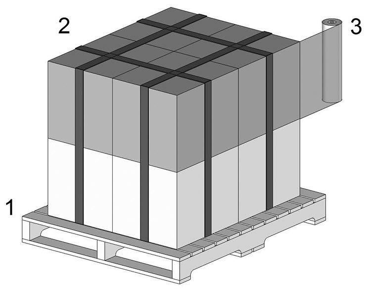
© Government of Canada, Canadian Conservation Institute. CCI 120714-0025
Figure 14. Palletizing individual packages can keep items together and can greatly reduce shock hazard intensity (the three steps for palletizing items are described above).
Shock during transport
Transport shock is considered a low-level hazard in all transport modes except rail. Note that this low-level hazard may still approach the equivalent of a 15 cm (6 in.) drop for packages that are firmly secured to the transport vehicle (truck). In the absence of restraint, this shock may be exceeded due to bouncing, falls and collision with other cargo items. Shocks during the take-off and landing of aircraft are low in intensity, with levels rarely exceeding 1.1 g’s.Endnote 17 Shocks that occur during railcar coupling can place significant loads on cargo, both due to the shock magnitude and to its ability to cause movement among massive cargo items.
General control strategies for transport shock
- Secure packages in all transport vehicles so that they will not move, fall or bounce repeatedly during transport.
- Ensure adequate strength of packaging (compressive strength, stiffness, etc.) for severe shock environments such as rail transport and for the transport of stacked items.
- Note that even low-level shock can induce movement among packages, among packed objects, among packaging components and in objects themselves.
- Packaged items may need to be able to withstand the equivalent of a 15 cm (6 in.) drop during shipment to ensure adequate protection against transport shock.
Vibration during transport
Transport will subject cargo to vibration and, unlike drops, which may or may not occur, the probability of full vibration exposure during transport is 100%. Common transport vehicles generate random vibration in the 1 Hz to 200 Hz frequency range. Random vehicle vibration is also considered a low-level source that does not usually cause strong or sustained responses (resonance) in susceptible objects, but it is still an important concern as it may cause movement and related effects, such as collision, abrasion and loosening of assemblies or fasteners.
In decreasing order of vibration intensity, the common modes of transport rank as follows: trucks, railcars, aircraft and ships. The transit vibration profiles of these four modes of transport are compared in Figure 15.Endnote 18 The vibration transfer efficiency between a package and the vehicle floor drops off at frequencies above 30 Hz, which is an asset, but low-frequency vibration can be transferred undiminished through the interface of the package to the floor and through foam materials, which is an important consideration for vulnerable art items. Vibration in this low-frequency range is also believed to be an important cause of damage during commercial product transport. Protective measures are described below (consult Vibration control methods).
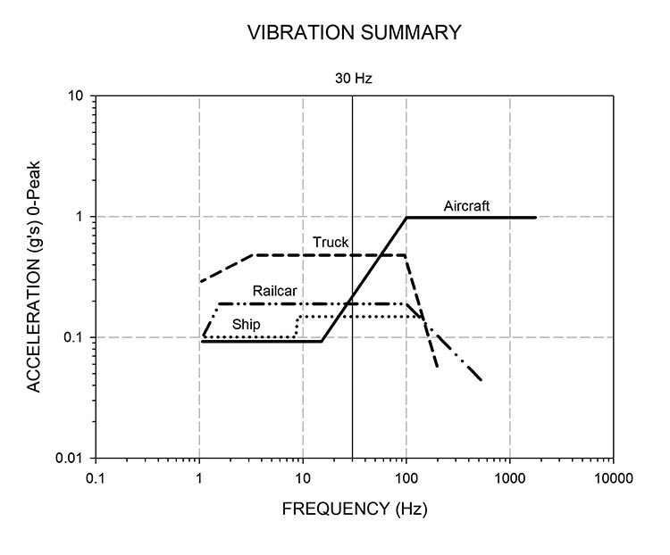
© Government of Canada, Canadian Conservation Institute. CCI 20714-0026
Figure 15. Transit vibration summary curves. These curves enclose peak levels for randomly occurring vibration. The effectiveness of vibration transfer between a package and the vehicle floor drops off at frequencies higher than 30 Hz.
Basic vibration terms and concepts
Vibration is motion relative to a fixed point of reference. It can be periodic, with motion that repeats at regular intervals, or random, with motion that varies randomly with time (such as vehicle vibration). Vibration is mainly a transport concern because most handling activities do not generate intense or sustained vibration.
Anything with mass and elasticity can vibrate. This leads to two concerns. The first is simply the ability of vibration to induce movement in objects, their parts and among the contents of a package. This can lead to abrasion, losses to fragile surfaces, collision between objects or between object parts, and loosening of parts at low-level forces that objects may otherwise sustain without adverse effects. The second vibration issue to consider is the deformation and strain that may be induced in vibrating items. If strain reaches a critical level, it can initiate damage or cause pre-existing damage to propagate. This is discussed in further detail below.
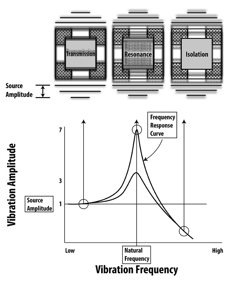
Objects or object parts capable of vibration may move at the same frequency and amplitude as applied transit vibration, and they may also have frequencies at which an amplified response to transit vibration may occur. The weight suspended by the spring in Figure 16 is a classic example of a simple system that can vibrate at one frequency. When the weight is displaced below its equilibrium position and released, the system will vibrate at resonant frequency. When this spring and mass combination is exposed to vibration, three outcomes are possible, depending on the frequency of the vibration source.
Transmission: When the source frequency is less than the resonant frequency, the weight will move at the same amplitude and frequency as the vibration source.
Resonance: When the source frequency is near the resonant frequency, the amplitude of the weight will increase to amplitudes that greatly exceed the source.
Isolation: When the source frequency is about two times greater than the resonant frequency, the amplitude of the weight will be less than that of the vibration source.
All three conditions are of interest in packaging. The transmission outcome explains how low-frequency transit vibration can travel through most packaging undiminished. Resonance is important because of force multiplying effects in affected objects and because cushion systems also have one frequency at which resonance may occur. The isolation outcome illustrates the vibration control property of a cushioning system.
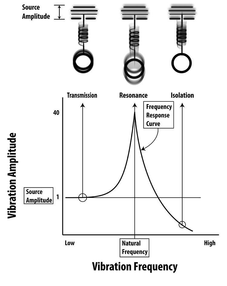
© Government of Canada, Canadian Conservation Institute. CCI 120714-0028
Figure 16. Response of a simple spring and weight combination to a source of periodic vibration having an amplitude of 1 across a range of frequencies; note the high resonant amplitude of an ordinary metal spring due to low damping.
Museum objects may have a number of vibration tendencies at different frequencies. Each vibration tendency will have a response that is similar to the simple spring mass combination described in Figure 16, with its own maximum resonant amplitude. Note that maximum object responses may be intermittent for the random vibration sources in transit vehicles.
Vibration cycling in objects or their parts
The most commonly appreciated damage effect of vibration is material fatigue. Bending a paper clip back and forth until it breaks is an example of this effect. During shipment, an object or its parts may be subjected to stress by vibration at transit amplitude or by transit amplitude amplified by resonance effects. In either case, fatigue damage is possible if
- stress rises above a critical threshold during each cycle of movement and
- a sufficient number of these stress cycles takes place.
A typical stress to failure curve (also known as an S-N or Wöhler curve) appears in Figure 17. It shows the relationship between the average numbers of cycles and material damage as obtained from tests on material samples. This curve illustrates the following:
- The higher the stress during each vibration cycle, the fewer the number of cycles leading to failure.
- Damage is cumulative when stress exceeds a critical threshold.
- Indefinite cycling without damage is possible if stress remains below a critical threshold.
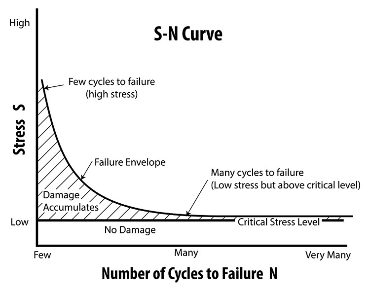
© Government of Canada, Canadian Conservation Institute. CCI 120714-0030
Figure 17. The S-N curve represents material damage thresholds against cyclic stresses. The general features of an S-N curve are shown above.
Two additional failure modes due to vibration are
- a large enough applied stress sustained for a sufficient amount of time and
- failure that takes place the first time a certain stress level is exceeded, as in the case of single-event damage due to shock.
Cracks and flaws in objects provide sites where stress can be concentrated. A paper clip can be broken in far fewer bending cycles if a small notch is filed into it prior to bending. Unfortunately, pre-existing damage is a common feature in many museum objects, and it may originate and progress due to a variety of causes. Ensuring the safe transport of damaged or flawed items can present challenges, and many carriers will have exclusions that limit their liability for specific object materials and types of pre-existing damage. Should such a shipment be unavoidable, the approach described in the section Shock protection for highly fragile items can be used to help minimize stress in vulnerable objects or assemblies.
Vibration damage thresholds and vibration sensitivity
Information on vibration damage thresholds for some types of canvas paintings is available.Endnote 19 Theoretical and experimental investigations indicate that strains during out-of-plane resonant responses to transit vibration are below the damage thresholds for some typical painting materials, although vibration-induced stretcher deformation and impact between a canvas and stretcher remain concerns.
When vibration damage thresholds are unknown, as will be the case for most art objects, a useful concept is vibration sensitivity. Vibration sensitivity is indicated by the presence of resonant frequencies in the transit range of 1 to 200 Hz. If identified, measures can be taken to reduce vibration tendencies, whether or not they are known to pose a damage risk. When doing this, low frequency vibration tendencies that involve larger displacements and strains should be addressed first; some of them may be indicated by obvious looseness, flexibility or movement in response to light tapping, etc.
Vibration control methods
There are three ways to control vibration:
- Source reduction
- Isolation
- Response alteration
Source reduction means avoiding unnecessary vibration exposure as discussed in the section Vibration during transport. This is always a good course of action because packaging treatments vary in their vibration control effectiveness and vulnerability in objects or their parts may not always be evident.
Isolation is possible using foam cushioning and mechanical devices such as slings or springs. Given that foam cushioning is the most common isolation medium in museum packing, this material will be discussed here.
An object floated on foam cushions is a simple mechanical system with one resonant frequency. Its behaviour is described by the curve in Figure 18, which has the same appearance as the response curve in Figure 16. The response of an object on a cushioning system to an external vibration source will also have three outcomes:
- vibration at frequencies below the cushion resonant frequency are transmitted through the cushioning system to the object undiminished
- vibration at frequencies near the resonant frequency of the cushion system are amplified
- vibration at frequencies at about twice the cushion resonant frequency are isolated
© Government of Canada, Canadian Conservation Institute. CCI 120714-0032
Figure 18. Vibration response curves for an object supported on protective cushions. Note the similarity to the response curve in Figure 16. The damping property of foam materials limits maximum resonant amplitude to values in the range of 3 to 7.
While foam cushioning systems do have a resonant frequency, foam materials also possess damping properties that limit resonant amplitude.Endnote 20 Typical foam cushion amplification factors range from 3 to 7 compared to 40 or more for ordinary metal springs.Endnote 21 Nonetheless, an overlap of cushion resonant frequency and strong object sensitivity should be avoided. Open-cell foam materials (for example, polyurethane foams) can provide better vibration isolation than those with a closed-cell structure, such as polyethylene. When referring to the isolation provided by a cushioning system, “effective” usually means a reduction of vibration source amplitude of 80% or more. Reference to cushion performance data for vibration (transmissibility curves) indicates that foam cushions can provide effective isolation at frequencies as low as 25 Hz to 35 Hz. Values near 45 Hz (polyurethane ester) and 55 Hz (polyethylene) are typical for the material thickness and static loads used in practice.Endnote 22 These frequencies may be lowered with tapered pads or ribs.Endnote 23
Effective vibration isolation using foam materials is not possible for all transit frequencies because effective isolation of low frequencies requires suspension systems with very large static deflections. A more practical alternative for addressing low-frequency susceptibility is to modify the behaviour of vibration-prone items (consult what follows on response alteration) in order to eliminate or reduce vibration tendencies or move them closer to the isolation region of the cushioning system.
Response alteration involves modifying a vibration-prone item to reduce its vibration tendency or increase the frequency at which it occurs. Examples of response alteration include:
- Disassembly (some artists design their works so they can be disassembled for shipment).
- Gentle restraint of vulnerable mechanical assemblies, flexible object parts and object/mount combinations (such as restraining the pendulum of a grandfather clock).
- Rolling large paintings or drawings into tubes of appropriate diameter.Endnote 24
- Protective wrapping (may offer restraint or damping).
- Increasing the contact area between a mount and an object stiffens this combination and reduces the load per unit area on a fragile surface.
- Using backing boards for small canvas paintings, stiff cardboard or matboard incorporated into wrapping methods so as to enclose the air cavity behind the canvas, which stiffens it and reduces oscillation amplitude.
- Packaging (the enclosed air space between the walls of a crate and canvas painting can have a stiffening effect on a canvas).
- Stretcher linings or backing boards with foam inserts for large canvas paintings limit large canvas oscillation and help avoid impact with cross braces.
- Treatment to strengthen weak objects, parts or surfaces.
- Securing/restraining of loose cargo in transit vehicles.
If undesirable responses or vulnerability in objects, their parts or object/mount combinations can be identified and corrected, an important cause of shock and vibration-related damage will be avoided. Effective cushions can then be designed for shock isolation with varying degrees of vibration isolation as a by-product.
General control strategies for transit vibration
- Contain or gently restrain large, loose or flexible vibration-prone items that may move and collide with other items during transport.
- Disassemble or modify larger, more massive vibration-prone items.
- Look for responsive substrates that may place lightweight, weakly adhered surface details at risk (as discussed in the section Shock) and apply alteration or isolation measures.
- Secure packages in transport vehicles during all transport scenarios, even short trips across town.
- Secure cargo with extra tie-down straps in case primary straps loosen.
- Avoid shipping display case units containing objects unless the cases are specially designed for transit.
- Use resilient material (thin foam, wrap, moving blanket, etc.) between unprotected (non-cushioned) objects or assemblies and the shipping vehicle interior to help filter out high-frequency vibration that may affect some mechanical components or fasteners. This interleave should be thin, and restraint measures should remain firm and secure.
- Select carriers with their own drivers and well-maintained fleets.
- Request air ride trucks and ensure that both the trailer and tractor unit of a tractor-trailer combination are air ride–equipped.
- Learn to identify the presence of air ride hardware on tractor units and trailers.
- Specify preferred locations in trucks (avoid over-the-wheel or rear overhang cargo placement), when possible, but address object vulnerability by treatment or in packaging as the first line of defence.
- Plan simple, direct journeys for highly susceptible items if basic packaging provisions are used; increase package treatment (for example, add cushioning for long-haul or complex journeys).
- Expect vibration exposure from equipment such as airport tug dollies with less effective suspension or the possibility that preferred vehicles may be substituted for others during parts of a complex shipment.
- Straight-frame air ride trucks may offer a smoother ride than trailers for individual items or partial loads.
- Transport critical shipments at lower speeds to help avoid unnecessary force exposure to the extent possible without compromising road safety.
- Select the best route for local or short moves of critical items that are lightly packed.
- Ensure that adequate protection is in place for items of concern through packaging or by other means, no matter which carriers are used (consult the section Vibration control methods).
- Air travel involves much less vibration exposure than trucks for long shipments.
- Be aware that equipment and road surfaces in foreign countries may differ considerably from familiar conditions.
Compressive forces
Compressive force can crush light packaging and may cause deformation or damage to larger crates. Compression can be a concern during transport and storage. During transport, the weight on the lowest containers in a stack will be multiplied by transit forces acting in the vertical direction. This load may be increased further by resonance effects in loosely stacked items. In storage, the lowest container in a stack carries the accumulated weight of all the containers placed on top. Other sources of compressive force include excessively forceful tie-down, shock during rail transport and loads imposed by handling equipment.
General control strategies for compressive forces
- Build or purchase strong wooden crates that meet applicable standards and that are capable of supporting minimum top loads of at least 244 kg/m2 (50 lb./sq. ft.) if stacking is anticipated (consult the section Wooden crates).
- Build crates with framing designed for compressive strength if high stacking loads are anticipated.
- Stack containers “like on like” to create an efficient load transfer path through vertical crate walls and framing down to the floor or vehicle bed.
- Build crates with features that permit efficient load transfer between stacked packages; for example, use skids and rub strips instead of individual feet that can concentrate loads.
- Use load bars or similar support provisions to create a second cargo level in trucks to fill trailers without having to stack dissimilar packages on top of each other.
- Avoid excessive force when applying restraints such as tie-down straps. Securing cargo does not need to be extremely forceful to be effective, but it does need to be firm, secure and unlikely to loosen. Use backup restraints in case primary tie-down straps loosen.
- Recognize the limitations of corrugated containers, especially in common distribution channels and damp conditions.
Puncture and blunt impact
Puncture is the result of concentrated loads acting on small areas of a package. Typical puncture causes include impact with small, solid items such as pipes, nails, pieces of lumber, the corner of another package or impact by forklift truck tines. Shipping containers may also receive blunt impacts from falling items, other containers or the sudden application of loads.
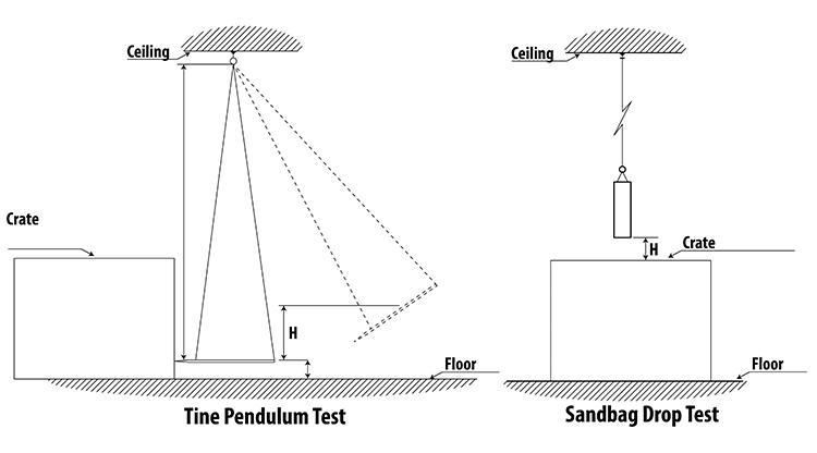
There is limited information in the packing literature on estimation methods for puncture or blunt impact because these hazards are not easy to observe or measure. Instead of intensity predictions, commercial package test methods evaluate package durability against a range of puncture and blunt impact hazards. Forklift puncture hazards are simulated by loading shipping containers to immobilize them and subjecting them to impact from swinging tines (pendulum tests). The ability of containers to withstand blunt impact loads is evaluated by various methods, such as the sandbag drop (Figure 19).
© Government of Canada, Canadian Conservation Institute. CCI 120714-0034
Figure 19. Impact tests for shipping crates (Andreason): fork tine impact test (left) and an ASTM E-72 sandbag drop (right). The fork tine test uses an actual forklift tine, while the sandbag drop test uses a 27 kg (60 lb.), 23 cm (9 in.) diameter sandbag.
General control strategies for puncture and blunt impact
- Build or purchase shipping containers that meet applicable standards for domestic or overseas shipment (consult the section Wooden crates).
- Use plywood for crate panels. Avoid lumber, oriented strand board and particleboard or similar materials unless the services of art handlers are used.
- Use double case systems for added protection against puncture (consult the section Double case packaging).
- Use quality transport and source-to-destination shipment if lighter crating construction or materials are used.
- Recognize the limitations of corrugated containers, especially in common distribution channels. Use stronger corrugated materials such as triwall and consider adding reinforcement features against blunt impact and puncture in vulnerable areas.
Temperature changes and extremes
Worst-case scenarios for uncontrolled transit are provided here for information purposes. Predictive models based on long-term weather data can be used to estimate the magnitude and duration of temperature extremes in the event of equipment malfunction for various locations and times of year. Simplified approaches based on ambient temperature are also possible.Endnote 25
During road transport, cargo temperature will lag behind maximum and minimum ambient values. A study of a 2.5-ton van travelling through cold regions of Canada and the western United States reported a minimum cargo temperature of −19°C (−2°F) when the minimum outdoor temperature reached an extreme of −29°C (−20°F).Endnote 26 The difference between the outside air and the cargo temperature over the entire 6600 km (4000 mi.) journey ranged from 0.5°C to 10°C (1°F to 18°F), with the cargo temperature always greater than the outdoor minimum temperature on any given day. The same investigation included five hot weather journeys covering a distance of 700 km (420 mi.) through Death Valley, California, in the same 2.5-ton truck. Measurements of cargo surface temperatures indicated values that were 6°C to 8°C (10°F to 14°F) below the maximum outdoor temperature of 54°C (129°F). The temperature in road vehicle cargo holds is highest when they are stationary and is moderated by vehicle movement. This effect is most pronounced in the summer, when air movement through and over a vehicle helps offset solar heat gain.
The temperature in aircraft cargo holds is maintained in the range of −1°C to 21°C (30°F to 70°F) when the aircraft systems are in operation. Minimum values are rarely lower than about 5°C (41°F), and values above 10°C (50°F) are typical. Some aircraft are equipped with multiple cargo holds with independent controls to accommodate different cargo temperature requirements. Cargo aboard an aircraft parked in freezing or very hot weather will eventually be subjected to outdoor ambient temperatures unless supplementary air conditioning systems are used. In worst-case scenarios, interior cargo temperatures for parked aircraft over a period of 36 hours can reach as high as 49°C (120°F) in desert conditions and as low as −29°C (−20°F) or lower in arctic conditions.
During ocean transport, average outside and cargo temperatures will follow each other closely. Cargo below deck will closely follow the seawater temperature. Items on deck and immediately below the deck may experience higher temperatures, for example, 53°C to 75°C (126°F to 167°F), due to solar radiation.
High and low temperatures for uncontrolled standing rail boxcars is a maximum of 49°C (120°F) for 2 hours and a minimum of −23°C (−10°F) for 36 hours. This data is comparable to the findings of recent investigations of cargo temperature inside 20-foot shipping containers.Endnote 27
Recent data-logger investigations show the range of temperatures that sensitive commercial cargo may experience during intermodal shipment.Endnote 28 Temperature extremes comparable to those mentioned above are reported for domestic summer and winter shipments in trucks (highs of 43°C [109°F] and lows near −15°C [5°F] respectively). Covering palletized cargo with insulating blankets can limit these extremes to 32°C (90°C) and −4°C (25°F).
For trans-oceanic shipment, both insulated and non-refrigerated containers quickly reached temperatures of 30°C (86°F) on the initial truck journey, before the ocean voyage even began. Cargo in refrigerated containers did not exceed 19°C (66°F) at any point in the journey, but the temperature control provisions are expensive and ocean journeys are long. There have been reports of occasional losses in commercial shipments due to equipment malfunction and improper temperature settings.
Temperature effects on objects and packaging
Protection against temperature extremes can be an important shipping feature for both susceptible items and packaging. Temperatures above or below safe limits can affect objects and packaging in ways that increase overall risk.
| Condition: incorrect temperature | Effect on objects | Effect on packaging |
|---|---|---|
| Low (< 15°C [59°F]) |
|
|
| High (> 25°C [77°F]) |
|
|
Note: The typical requirement for temperature is reliable control in the range of 15°C to 25°C (59°F to 77°F).
| Condition: Incorrect humidity | Effect on objects | Effect on packaging |
|---|---|---|
| Low (< 25%) |
|
|
| High (> 65%) |
|
|
Temperature control during shipment
Packaging and vehicle cargo holds can delay (buffer) temperature changes and limit extremes, but heating or cooling systems are required in transport vehicles for medium to long journeys in cold and hot weather. The typical temperature control specification for art shipments is reliable control within a range of 15°C (59°F) to 25°C (77°F). Investigations of temperature-controlled art shipments with loggers have not recorded interior case temperatures below 11°C (52°F).Endnote 31
Thermal buffering
Thermal buffering is a beneficial feature that is made possible by the insulating ability of a package. This controls the rate of temperature change and the time it takes for package contents to fully respond to an external temperature change. It also contributes to effective humidity buffering (discussed below). Thermal buffering can be expressed as the half-time (in hours) required for the contents of a package to reach a temperature that is mid-way between the package’s initial temperature and a new temperature to which it is exposed. Table 12 provides examples of package half-times and the half-time concept.
© Government of Canada, Canadian Conservation Institute. CCI 120714-0038
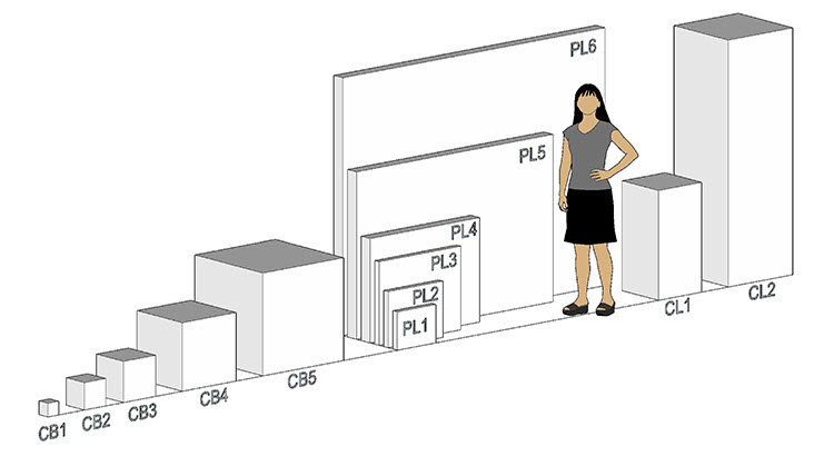
Figure 20. The object sizes shown to scale here are used for thermal and humidity buffering examples in Tables 12, 13 and 15. Object dimensions and volume are shown in Table 11.
| Object | Dimensions (cm) | Volume (m3) | Dimensions (in.) | Volume (cu. ft.) |
|---|---|---|---|---|
| CB1 | 10 x 10 x 10 | 0.001 | 4 x 4 x 4 | 0.04 |
| CB2 | 20 x 20 x 20 | 0.008 | 8 x 8 x 8 | 0.30 |
| CB3 | 30 x 30 x 30 | 0.027 | 12 x 12 x 12 | 1.00 |
| CB4 | 51 x 51 x 51 | 0.133 | 20 x 20 x 20 | 4.63 |
| CB5 | 76 x 76 x 76 | 0.439 | 30 x 30 x 30 | 15.63 |
| PL1 | 28 x 36 x 5 | 0.005 | 11 x 14 x 2 | 0.18 |
| PL2 | 41 x 51 x 5 | 0.010 | 16 x 20 x 2 | 0.37 |
| PL3 | 61 x 76 x 5 | 0.023 | 24 x 30 x 2 | 0.83 |
| PL4 | 76 x 102 x 10 | 0.078 | 30 x 40 x 4 | 2.78 |
| PL5 | 122 x 183 x 10 | 0.223 | 48 x 72 x 4 | 8.00 |
| PL6 | 188 x 244 x 10 | 0.459 | 74 x 96 x 4 | 16.44 |
| CL1 | 81 x 41 x 41 | 0.136 | 32 x 16 x 16 | 4.74 |
| CL2 | 178 x 61 x 61 | 0.662 | 70 x 24 x 24 | 23.33 |
Package insulating ability
The insulating ability of a package is related to a number of factors; among these, shape and wall thickness are most significant. Wall thickness controls heat transfer by conduction, and surface area determines the rate of heat transfer by convection and radiation. The best shape a package can have for retaining heat is a cube, because it has the smallest surface area to volume ratio. Beyond shape and wall thickness, the following factors also contribute to insulating ability:Endnote 32
- Multi-layered walls: For any given wall thickness, multi-layered walls that trap a small air space between layers will perform better than one thick wall. A thin (less than 10 mm [0.393 in.]) trapped air layer provides a significant resistance to heat flow.
- Contact area between object and package: The contact area between the object and the package affects insulating ability. Packages with thin walls may experience substantial heat loss or gain in areas where the packaged object is in contact with the container wall.
- Heat capacity: The amount of heat contained in an object contributes to package insulating ability. Large, massive items retain substantial quantities of heat. By comparison, the heat capacity of dry hygroscopic materials is low.
- Foil barriers: Foil barriers control heat loss or gain by radiation and improve the insulating ability of the package. The effect of foil barriers is greatest for packages with thin walls.
- Seal details: Seal details play an important part in insulating ability. Poorly sealed crates can experience heat loss or gain by air leakage, which can work against the benefits of good insulation.
- Temperature difference: The smaller the difference between the package and its environment, the greater the insulating ability.
The insulating ability of most museum packaging is often limited by
- a less than ideal shape (such as tall, narrow crates for paintings),
- low heat capacity of the package contents (this property applies to many object types) and
- practical constraints on packaging treatment (package size, fabrication costs, shipping costs, etc.).
As a result, the thermal half-time of the typical museum package is often in the range of one to three hours, as shown in Table 12. When better performance is necessary, insulating material (25–50 mm [1–2 in.]) or added cushion thickness (cushioning materials are good insulators) can increase these half-times to two to six hours or more.Endnote 33
Half-time examples of packages for the range of object sizes shown in Figure 20 are provided in Table 12.Endnote 34 This information indicates a possible risk for some packaging scenarios in a matter of hours or less if transport vehicle heating or cooling equipment malfunctions under extreme conditions. Well-maintained fleets and backup temperature control systems as well as planned emergency procedures can contribute to safe shipment.
| Object | 50 mm (2 in.) flexible polyurethane foam on all sides (hours) |
50 mm (2 in.) flexible polyurethane cushioning and 25 mm (1 in.) rigid polystyrene insulation inside crate (hours) |
50 mm (2 in.) flexible polyurethane cushioning and 50 mm (2 in.) rigid polystyrene insulation inside crate (hours) |
|---|---|---|---|
| CB1 | 1.4 | 1.7 | 2.1 |
| CB2 | 3.0 | 3.8 | 4.6 |
| CB3 | 4.7 | 5.9 | 7.2 |
| CB4 | 8.0 | 10.2 | 12.4 |
| CB5 | 12.1 | 15.5 | 18.8 |
| PL1 | 1.7 | 2.2 | 2.6 |
| PL2 | 1.9 | 2.4 | 2.9 |
| PL3 | 2.1 | 2.6 | 3.2 |
| PL4 | 3.9 | 5.0 | 6.0 |
| PL5 | 4.3 | 5.4 | 6.6 |
| PL6 | 4.5 | 5.7 | 6.9 |
| CL1 | 7.7 | 9.8 | 11.9 |
| CL2 | 12.5 | 15.9 | 19.3 |
Note: The contents are assumed to be bulk hygroscopic materials that occupy 25% of the package volume and have a mass density of 500 kg/m3 (31 lb./cu. ft.). The times shown are examples of the time it takes for the temperature of the package contents to change halfway from a given temperature to a new temperature to which the package is suddenly exposed. The influence of package shape on insulating ability can be seen by comparing packages of similar weight but different shape. Most typical packaging brought into a museum from another environment will reach ambient temperature in 12 to 24 hours.
Insulating ability may be improved in the following ways:
- Grouping several items in a double case system can increase the effective heat capacity of the package contents and the possibility of approaching a more efficient cube shape. This is apparent in the performance of items CB5 and PL6 in Table 12, which have similar content weight and heat capacity.
- Externally applied insulation makes use of the heat capacity of the shipping container materials and package contents (the heat capacity of the shipping container is neglected for values in Table 12).Endnote 35
- Skids or spacers between a crate and cold vehicle sidewall minimize direct contact between packaging and cold surfaces and improve air circulation.
- The use of phase change materials.Endnote 36
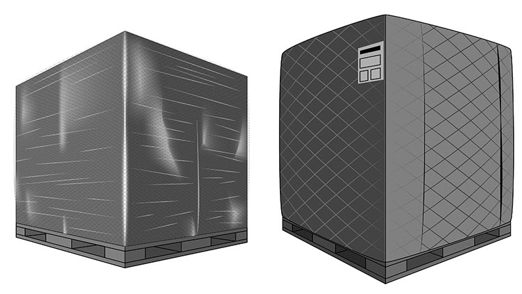
© Government of Canada, Canadian Conservation Institute. CCI 120714-0039
Figure 21.Insulated covers. Left: lightweight reflective bubble sheet. Right: nylon with high loft insulation fill.
Cold chain shipment
For the shipping of items such as live culture collections that have cold chain maintenance requirements similar to vaccines (2°C to 8°C [36°F to 46°F]), polystyrene coolers with thick walls (30–80 mm [1.2–3.2 in.]) and tight-fitting lids are available from packaging material suppliers. The use of these coolers plus a suitable quantity of phase change material (such as ice or gel packs) can maintain cold temperatures for 30 to 48 hours or more.
The temperature of gel packs coming out of a freezer (after 12 hours) or a domestic refrigerator freezer (after 24 hours) can be as low as -18°C (-0.4°F), with reports of possible freezing within the first two hours after having packed the items in the cooler. Guidelines for the safe shipment of vaccine-type materials recommend a conditioning procedure for ice or gel packs prior to packing, plus the inclusion of a buffer between the cold packs and temperature-sensitive items.Endnote 37
- To condition ice packs:
- Remove ice packs from the freezer and lay them in a row (on their short sides, if possible) with about 5 cm (2 in.) of space between each pack for air circulation.
- Allow ice packs to stand until they begin to sweat (approximately 1 hour at 20°C [68°F] or much less at a higher temperature).
- An ice pack is conditioned at the onset of water “sloshing” inside the pack.
- To condition gel packs:
- Remove gel packs from the freezer and lay them in a row (on their short sides, if possible) with about 5 cm (2 in.) of space between each pack for air circulation.
- Allow gel packs weighing less than 750 [grams] (1.65 lb.) to stand for 45 minutes (at room temperature of 15°C [59°F] or more) or 1 hour (room temperature less than 15°C [59°F]).
- Allow gel packs weighing more than 750 [grams] (1.65 lb.) to stand for 1 hour (at room temperature of 15°C [59°F] or more) or 1.5 hours (room temperature less than 15°C [59°F]).
— Source: Australian Government Department of Health and Ageing, 2005
General control strategies for temperature
- Anticipate the effects that temperature can have on both the objects and protective packaging (consult the section Temperature changes and extremes).
- Most packaging treatment will offer some thermal buffering. Add thermal insulation to improve insulating ability if necessary (consult the section Thermal buffering).
- Provide reliable temperature-controlled transport within a range of 15°C (59°F) to 25°C (77°F) and, if possible:
- a backup heating and cooling system, in the event of main unit failure,
- ducting and air circulation in the trailer or cargo area,
- insulated walls for trucks and trailers,
- space between the cargo and a cold wall (spacers) and floor surfaces (skids) in trucks and trailers (even if insulated), while ensuring proper cargo restraint (for air circulation during long cold weather shipments) and
- emergency access to warehouses or other suitable facilities along a proposed route (this may be arranged in advance of critical shipments).
- Cover packages or groups of packages with insulating quilts, blankets or other forms of insulation.
- Surround packages containing temperature-sensitive items with non-sensitive cargo to act as a buffer.
- Avoid contact between temperature-sensitive materials or finishes on an object and packaging material (such as air-encapsulated film, which can stick to painting materials or other materials at elevated temperatures).
Humidity changes and extremes
Humidity conditions vary widely over the course of a shipment and in storage facilities or warehouses. Air transport represents the low end of the transit humidity extremes at 10–20% RH. Ocean transport is at the high end, with conditions approaching saturation, or 100% RH, which can lead to condensation and water damage (container rain) that can affect both the packages and the items they contain.
Humidity buffering
Humidity buffering is a passive feature (it does not require mechanical systems) that can protect hygroscopic materials from moisture gains or losses during shipment. Many packaged items containing about 25% or more (by volume) of hygroscopic material, such as wood (unpainted, no coatings), matboard, paper or leather, may be well protected by self-buffering mechanisms and temperature control during typical transit and storage time frames. This is made possible by the following features, which are specific to a packaging scenario:
- The use of effective moisture barrier materials such as polyethylene wrap.
- The small volume of air enclosed between the moisture barrier and the object.
- The large moisture reserves in objects compared to the surrounding air in a closed package or vapour barrier wrap.
- The short time frame of most shipping and warehousing activities (compared to permanent museum exhibits).
Humidity buffering inside a package
The moisture content of hygroscopic objects on open display is driven by ambient environment conditions, with RH having the greatest effect. Hygroscopic materials in packages, in contrast, often contain much more moisture than the small surrounding volume of air. Temperature changes can initially change the RH of this air volume (consult Temperature and humidity loggers), but equilibrium conditions at the new temperature will be re-established with very little moisture gain or loss between the object and the surrounding air.Endnote 38 Accordingly, both the object moisture content changes and the related dimensional changes are limited.
Example:
A framed canvas painting 72 cm x 72 cm x 5 cm (28 in. x 28 in. x 2 in.) in size, weighing 5 kg (11 lb.), contains about 0.51 kg (1.12 lb.), or about 10,200 drops, of water at 20°C (68°F) and 50% RH. When the painting is closely wrapped in polyethylene, the enclosed air volume (headspace) contains about four drops of water. For a temperature increase to 30°C (86°F), the headspace equilibrium RH will increase to 52.4% with three drops of water released from the painting. For a drop to 10°C (50°F), the headspace equilibrium RH will drop to 48.3% and about four drops of water will be adsorbed by the painting. In both cases, the painting moisture content remains virtually unchanged at about 9.3%.Endnote 39
Humidity buffering and package leakage
Packaged items will gradually experience changes in humidity and moisture content due to three leakage mechanisms, listed in decreasing order of contribution:Endnote 40
- infiltration of air through gaps, holes or seams;
- permeation of moisture through packaging materials; and
- diffusion of moisture through gaps and holes.
The effect of all three mechanisms combined is case leakage, which can be expressed in the quantity of air changes per day. Table 13 shows that leakage rates of well-constructed plywood containers are much higher than that of wrapping in polyethylene sheet material. Commercially available plastic shipping containers have very low leakage rates, and some manufacturers supply data on water vapour transmission rates (WVTR). CCI has developed leakage and humidity calculation tools for enclosures that can be used to evaluate how different packaging scenarios perform in different external conditions.Endnote 41 These tools are useful for predicting package performance during transit as well as periods of storage, and they were used to estimate the humidity buffering ability performance of packaging scenarios in Tables 13 and 15.
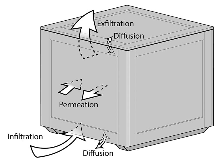
© Government of Canada, Canadian Conservation Institute. CCI 120714-0040
Figure 22. The three leakage mechanisms for a package: infiltration, exfiltration and diffusion through cracks or holes and permeation through materials. Arrow sizes illustrate the relative contribution of each mechanism.
Unwrapped objects in a wooden shipping crate
Table 13 provides examples of the humidity buffering ability of well-constructed plywood shipping crates (not accounting for the buffering contribution of wood crate material). It indicates the time required for a 2.5% change in RH for three buffer content percentages.
| Object description (Figure 20) |
Crate leakage (air changes per day) |
10% buffer content |
25% buffer content |
50% buffer content |
|---|---|---|---|---|
| CB1 | 16.8 | 3 | 7 | 14 |
| CB2 | 10.3 | 4 | 11 | 22 |
| CB3 | 7.5 | 6 | 15 | 30 |
| CB4 | 4.8 | 9 | 23 | 47 |
| CB5 | 3.3 | 14 | 35 | 68 |
| PL1 | 12.6 | 4 | 9 | 17 |
| PL2 | 10.9 | 4 | 10 | 20 |
| PL3 | 9.4 | 5 | 12 | 24 |
| PL4 | 7.0 | 6 | 16 | 31 |
| PL5 | 6.0 | 7 | 19 | 37 |
| PL6 | 5.9 | 8 | 20 | 38 |
| CL1 | 5.0 | 9 | 23 | 45 |
| CL2 | 3.2 | 14 | 35 | 68 |
* Object initially in equilibrium with 50% RH inside a 12 mm plywood crate (painted interior and exterior). Times shown are predictions in days for object equilibrium with 52.5% RH or 47.5% RH for exposure to high (85%) or low (15%) RH. For additional information, consult endnotes.Endnote 42
Although not accounted for in Table 14, uncoated interior wood crate surfaces can contribute to buffering ability, but several issues need to be kept in mind when making use of this feature:
- Crates need to be stored in a controlled environment (this is still advisable for wrapped items).
- Acids released by wood into the closed crate environment may rise to levels that could pose a risk to some object materials.
- Package contents are more vulnerable to water and pest entry.
If the packer does not wish to wrap objects, a vapour barrier coating can be applied to the crate interior. Buffering performance can then be improved with the addition of bulk hygroscopic material or silica gel inside the crate (consult Silica gel).
Wrapping, barrier materials and water vapour transmission rate
The WVTR is a common measure of moisture barrier effectiveness for packaging applications. Several WVTR values are shown in Table 14. The performance of barriers can be categorized as follows:
- high performance: < 0.5 g/m2/24 hr (0.032 g/100 sq. in./24 hr)
- medium performance: 0.5 to 5 g/m2/24 hr (0.032 to 0.322 g/100 sq. in./24 hr)
- low performance: > 5 g/m2/24 hr (0.322 g/100 sq. in./24 hr)
Polyethylene wrap is commonly used as a vapour barrier. It is readily available and its performance is well suited to transit time frames and mid-range humidity (45% to 50%) requirements. For long transit cycles, long-term storage or low humidity requirements, high performance barriers such as Marvelseal or Escal may be considered, with choices between these materials made on whether there is a need or advantage (such as customs inspection) for the contents to remain protected and visible (Escal) or not (Marvelseal).
Wrapping materials are used for a number of applications beyond humidity buffering, such as basic protection, excluding dust and avoiding direct contact with fragile surfaces. Materials such as Mylar, Dartek and Tyvek may be used for such purposes but are not considered effective vapour barriers (Table 16).
| Flexible barrier material | WVTR g/m2/24 hr | WVTR g/100 sq. in./24 hr |
|---|---|---|
| Marvelseal 360 5.2 mils | 0.01 | 0.0005 |
| Escal 4.5 mils | 0.01 | 0.0006 |
| Polypropylene (oriented) 1 mil | 2.50 – 6.20 | 0.16 – 0.40 |
| Polyethylene (high density) 1 mil | 4.65 – 7.75 | 0.30 – 0.50 |
| Polypropylene (cast) 1 mil | 4.90 – 8.70 | 0.31 – 0.56 |
| Polyethylene (low density) 1 mil | 15.50 – 23.25 | 1.00 – 1.50 |
| Mylar (PET, polyester) 1 mil | 27.90 | 1.80 |
| Dartek (nylon 6/6) 1 mil | 295 | 19 |
Notes:
- WVTR data test conditions vary among sources for listed materials. Most are 90% RH, 100°F, except Dartek (90%, 23°C [73°F]) and Escal (60% RH, 25°C [77°F]).
- Polypropylene cast and oriented test conditions are not listed in source table.Endnote 43
- For thicker homogenous barrier materials, the normalized values (1 mil) can be divided by total film thickness in mils.
Wrapped objects in a wooden shipping crate
Humidity buffering values for a 2.5% increase or drop in interior RH for wrapped objects inside a wooden crate are shown in Table 15. Substantial improvement is seen over the times in Table 13, provided that the polyethylene wrapping is well sealed and free of defects. The buffering ability of the uncoated shipping case interior is not considered in these examples.
| Object description (Figure 20) |
Leakage (air changes per day) |
10% buffer content |
25% buffer content |
50% buffer content |
|---|---|---|---|---|
| CB1 | 3.1 | 15 | 35 | 73 |
| CB2 | 1.6 | 27 | 70 | 145 |
| CB3 | 1.0 | 42 | 104 | 208 |
| CB4 | 0.6 | 70 | 173 | 348 |
| CB5 | 0.4 | 105 | 254 | 523 |
| PL1 | 2.7 | 16 | 42 | 83 |
| PL2 | 2.5 | 18 | 43 | 90 |
| PL3 | 2.4 | 19 | 47 | 95 |
| PL4 | 1.3 | 34 | 89 | 175 |
| PL5 | 1.2 | 38 | 94 | 189 |
| PL6 | 1.2 | 38 | 96 | 191 |
| CL1 | 0.7 | 67 | 168 | 336 |
| CL2 | 0.4 | 104 | 268 | 542 |
* Object initially at 50% RH wrapped inside 4-mil polyethylene. Times shown are predictions in days for object equilibrium with 52.5% RH or 47.5% RH for exposure to high (85%) or low (15%) RH. Buffering ability may vary according to wrapping methods and material properties. Buffer material used for calculations is paper in bulk. For additional information, consult the endnotes.Endnote 44
Fast-acting buffers
Rates of moisture transfer for different hygroscopic materials may vary for a given change in humidity. This has led to concerns about the possibility of a large mass of one material, such as wood, driving humidity changes to the detriment of a minor component with a different moisture response.Endnote 45 Although investigations indicate that this is an unlikely issue in practice, a solution for any item of concern would be to wrap the item in a layer of acid-free tissue or cotton before wrapping it in a moisture barrier to provide a fast-acting buffer.Endnote 46
Silica gel
Silica gel can be used to create low-humidity packaging or to supplement the hygroscopic content of packaged objects. Silica gel desiccant can be purchased from packaging material suppliers in convenient “unit” packs made of kraft paper or Tyvek.Endnote 47 Tyvek is preferred for its superior tear resistance and ability to contain dust from the desiccant material. Gram sizes are also available for package volumes of 950 mL (32 oz.) or less. Desiccant pack materials allow easy regeneration of the desiccant material (by heating) without the need to remove it from the package.
The WVTR requirement for low-humidity packaging for long-term storage is 0.075 g/m2/24 hr (0.005 g/100 sq. in./24 hr) or better. This WVTR, combined with the desiccant quantities in Table 15, can maintain low humidity conditions for periods of 18 months to 2 years.Endnote 48 Rigid containers capable of meeting such low WVTR requirements are usually made of metal. Flexible barriers would need to be made of high-performance materials such as Escal and Marvelseal.
| Commercially available desiccant “units”* | cm2 | m2 | sq. in. | sq. ft. |
|---|---|---|---|---|
| 1/6 | 98 | 0.01 | 15 | 0.10 |
| 1/3 | 196 | 0.02 | 30 | 0.21 |
| 1/2 | 293 | 0.03 | 45 | 0.31 |
| 1 | 587 | 0.06 | 91 | 0.63 |
| 2 | 1173 | 0.12 | 182 | 1.25 |
| 4 | 2346 | 0.23 | 364 | 2.50 |
| 8 | 4692 | 0.47 | 727 | 5.00 |
| 10 | 5865 | 0.59 | 909 | 6.25 |
| 16 | 9384 | 0.94 | 1455 | 10.00 |
| 80 | 46,921 | 4.69 | 7273 | 50.00 |
* 1 unit = 28 grams
| Commercially available desiccant “units”* | cm3 | m3 | cu. in. | cu. ft. |
|---|---|---|---|---|
| 1/6 | 3902 | 0.003 | 238 | 0.14 |
| 1/3 | 7804 | 0.01 | 476 | 0.28 |
| 1/2 | 11,705 | 0.01 | 714 | 0.42 |
| 1 | 23,411 | 0.02 | 1429 | 0.83 |
| 2 | 46,822 | 0.05 | 2857 | 1.67 |
| 4 | 93,643 | 0.09 | 5714 | 3.33 |
| 8 | 187,287 | 0.19 | 11,429 | 6.67 |
| 10 | 234,109 | 0.23 | 14,286 | 8.33 |
| 16 | 374,574 | 0.37 | 22,857 | 13.33 |
| 80 | 1,872,869 | 1.87 | 114,286 | 66.67 |
* 1 unit = 28 grams
Precautions for wrapped objects
Wrapping items equilibrated to RH levels of 70% or more should be avoided, as this can increase the risk of condensation.Endnote 49 When nearing such a condition, the presence of a fast-acting buffer such as acid-free tissue between the object and its wrapping can reduce the risk.
Most museum packaging will come into thermal equilibrium with the ambient environment within a 12- to 24-hour time frame (Table 12). If there is a need to unpack items quickly, care is necessary to ensure that condensation will not occur on a cold object that is at or below the dew-point temperature of the museum air.
Table 18 can be used to predict condensation risk with information on object temperature, indoor ambient temperature and humidity values.Endnote 50 The dew-point temperature can also be estimated for other conditions using a simple equation.Endnote 51 Wrapped items may be uncrated sooner than unwrapped items, but they should not be unwrapped until they are above the dew-point temperature and brought into the correct humidity environment. Infrared thermometers can be used for quick and easy object temperature measurements.
| Indoor temperature |
Indoor RH 25% |
Indoor RH 30% |
Indoor RH 35% |
Indoor RH 40% |
Indoor RH 45% |
Indoor RH 50% |
Indoor RH 55% |
Indoor RH 60% |
|---|---|---|---|---|---|---|---|---|
| 16°C (61°F) |
-4°C (25°F) |
-2°C (29°F) |
1°C (33°F) |
2°C (36°F) |
4°C (39°F) |
6°C (42°F) |
7°C (45°F) |
8°C (47°F) |
| 17°C (63°F) |
-3°C (26°F) |
-1°C (31°F) |
1°C (35°F) |
3°C (38°F) |
5°C (41°F) |
7°C (44°F) |
8°C (46°F) |
9°C (49°F) |
| 18°C (64°F) |
-2°C (28°F) |
0°C (32°F) |
2°C (36°F) |
4°C (40°F) |
6°C (43°F) |
7°C (45°F) |
9°C (48°F) |
10°C (50°F) |
| 19°C (66°F) |
-2°C (29°F) |
1°C (34°F) |
3°C (38°F) |
5°C (41°F) |
7°C (44°F) |
8°C (47°F) |
10°C (50°F) |
11°C (52°F) |
| 20°C (68°F) |
-1°C (31°F) |
2°C (35°F) |
4°C (39°F) |
6°C (43°F) |
8°C (46°F) |
9°C (49°F) |
11°C (51°F) |
12°C (54°F) |
| 21°C (70°F) |
0°C (32°F) |
3°C (37°F) |
5°C (41°F) |
7°C (44°F) |
9°C (48°F) |
10°C (50°F) |
12°C (53°F) |
13°C (55°F) |
| 22°C (72°F) |
1°C (34°F) |
4°C (39°F) |
6°C (43°F) |
8°C (46°F) |
10°C (49°F) |
11°C (52°F) |
13°C (55°F) |
14°C (57°F) |
| 23°C (73°F) |
2°C (35°F) |
5°C (40°F) |
7°C (44°F) |
9°C (48°F) |
10°C (51°F) |
12°C (54°F) |
14°C (56°F) |
15°C (59°F) |
| 24°C (75°F) |
3°C (37°F) |
5°C (42°F) |
8°C (46°F) |
10°C (49°F) |
11°C (52°F) |
13°C (55°F) |
14°C (58°F) |
16°C (60°F) |
| 25°C (77°F) |
4°C (39°F) |
6°C (43°F) |
9°C (47°F) |
11°C (51°F) |
12°C (54°F) |
14°C (57°F) |
15°C (60°F) |
17°C (62°F) |
| 26°C (79°F) |
4°C (40°F) |
7°C (45°F) |
9°C (49°F) |
11°C (53°F) |
13°C (56°F) |
15°C (59°F) |
16°C (61°F) |
18°C (64°F) |
| 27°C (81°F) |
5°C (42°F) |
8°C (46°F) |
10°C (51°F) |
12°C (54°F) |
14°C (57°F) |
16°C (60°F) |
17°C (63°F) |
19°C (65°F) |
Note: Avoid removing items from packaging until they are above these temperatures to reduce the risk of condensation on cold object surfaces. Values outside of ranges shown can be estimated with a simple equation (consult endnote 38).
General control strategies for humidity
- Ensure that the packaging materials and the enclosed hygroscopic material content provide adequate buffering for the duration of the transit or storage time frame (consult Tables 13 and 15).
- Provide additional buffering material in packages for items with small amounts of hygroscopic material and for unwrapped items in crates, if necessary (consult the section Humidity buffering).
- When additional buffering material is required, silica gel desiccant (preferably bead form) is preferable to clay desiccants, as it generates less dust and releases adsorbed moisture at a higher temperature.
- Use desiccants and high-performance moisture-barrier materials to maintain low-humidity conditions for long periods of time.
- Wrap humidity-sensitive items in a moisture-barrier material such as 4-mil polyethylene to improve buffering ability, but ensure that the items are conditioned to the proper RH before wrapping and that the wrapping provides a good seal.
- Avoid wrapping items equilibrated to humidity levels of 70% or higher, as this will increase the risk of condensation.
- If items are equilibrated to a high humidity level (but below 70%), a layer of adsorbent paper or tissue inside polyethylene wrapping can be used for added protection against condensation.
- Provide packaging that allows the time humidity buffering mechanisms need to work effectively in the event of rapid temperature changes. Typical packaging may be adequate, but light primary treatments such as wrapping alone may not. Avoid cold spots on light packaging where condensation may occur.
- Avoid high temperatures (greater than 25°C [77°F]), which may release moisture reserves in objects and desiccant materials.
- Build or purchase shipping containers with good construction details to help minimize air exchange (leakage) rates (consult the section Wooden crates).
- Paint exterior surfaces of wooden shipping containers to reduce moisture transfer by permeation (any paint is suitable for outer crate surfaces; consult the section Pollutants).
- Store wooden shipping containers in humidity-controlled storage areas that avoid dampness and RH extremes, especially if they are used to transport unwrapped items.
- For intermodal containers:Endnote 52
- load cargo warm,
- load cargo dry,
- control the intermodal case environment by using active systems or desiccants specially designed for use in intermodal containers over long ocean journeys (such as calcium chloride that sequesters absorbed moisture) and
- evaluate the quality and seal details of the intermodal containers.
- Note that humidity can affect packaging materials. For example, an increase in humidity from 40% to 90% results in a 50% loss in the stacking strength of cardboard.
- Protect labels with a transparent covering or paint information directly onto crates to keep exterior labels and markings from becoming illegible over time. Place destination information inside packaging as an added precaution.
- Request transport with reliable temperature control between 15°C and 25°C (59°F to 77°F) for art shipments.
Water
Water hazards include rain, snow, standing water at transfer points, vehicle or container damage that allows ingress of rain water or melting snow, condensing conditions (container rain) during ocean transport, and sprinkler discharge or exposure to high water volume in the event of firefighting activities.
General control strategies for water
- Avoid corrugated cardboard containers if there is a risk of water exposure or contact, or use protective wrapping (such as shrink wrap). Use coated corrugated materials for moisture protection.
- For wooden crates and containers (consult the section Wooden crates):
- Equip crates with feet and skids to keep container bases above wet floor surfaces.
- Ensure good detailing in crate construction to avoid water ingress (consult construction details in crate standards, such as ASTM D6251).
- Provide crates with well-fitted lids, gaskets and positive closure to prevent water ingress.
- Use plywood with glues that can handle moisture, as designated by the “X” in CDX (typically used for sheathing under roofs and exterior siding) and ACX (higher grade exterior plywood with smooth paintable surfaces). Medium density overlay, or MDO, is also moisture-resistant and is typically used for exterior road signage.
- Inspect the quality of intermodal containers, if possible. Consult Safe Storage: A Guide for Exporters for further information.
- Wrap objects (with polyethylene wrap, for example) as a second line of defence against water that may enter the primary shipping container.
- When packaged items are not wrapped, apply barrier materials or appropriate coatings to the shipping case interior (consult the next section for suitable coatings).
Pollutants
Pollutants include gases and volatile compounds; viscous compounds, such as plasticizers and grease; as well as solids, such as dust and salts. Dirt in work areas, material storage areas and even exhibit halls may find its way into packaging. Dust on the surface of metal objects may contain salts that can deliquesce, raise local humidity levels and accelerate the corrosion rate of the metal in the vicinity of the dust. Dust may also be abrasive and time-consuming to remove.
Packaging materials that come into contact with objects must be carefully selected to avoid adverse chemical reactions, staining or other effects on surfaces. The presence of plasticizers or release compounds (used during manufacturing) on materials such as some types of plastic sheeting may transfer chemicals onto object surfaces over time. Wood packaging material, unsuitable paints and coatings can release (or off-gas) volatile compounds (such as acetic acid) which can accumulate inside the closed environment of a shipping container and may reach levels that present a risk to susceptible items during long storage periods.
General control strategies for pollutants
- Maintain clean work areas.
- Keep packaging materials clean.
- Wash moving blankets on a regular basis.
- Clean object surfaces (such as marble) before packing to keep dirt from becoming embedded in porous object surfaces under the forces applied by packing materials. Seek conservator assistance to identify the best cleaning materials and methods.
- Clean metal surfaces before packing to remove dust and possible salt deposits that create localized high humidity sites and cause corrosion, especially if long storage periods are anticipated. Seek conservator assistance to determine the best cleaning methods and materials.
- Use clean transport vehicles and shipping containers.
- Use sorbent materials such as activated charcoal or material such as silver-impregnated cloth to protect metals enclosed in protective packaging that may be at risk from the accumulation of pollutants.
- Vacuum dust from foam pad components after cutting, especially polyurethane foam dust, which may react with some metal object materials or surfaces.
- Use stable materials for packing. Pay special attention to materials in direct contact with object surfaces (avoid direct contact between objects, object surfaces and polyurethane foam; avoid polyurethane foam for long-term storage).Endnote 53
- Examples of stable materials for short- and long-term use
- PE – polyethylene (Ethafoam, Plastazote, Tyvek)
- PP – polypropylene
- PS – polystyrene
- Acrylic
- Inert polyester films and sheet materials
- Acid-free tissue or card
- Polyester film (Secol, Mylar, Melinex)
- Inert foam (Plastazote, Ethafoam)
- Unbleached and undyed cotton or calico
- Correx
- Heat-bonded polyester wadding
- Examples of materials to avoid
- PVC – poly(vinyl chloride)
- PVAC – poly(vinylidene)
- PVA – poly(vinyl acetate)
- Acidic polyesters
- Chloroprene (neoprene)
- Urea-formaldehyde panels
- Non–acid-free tissue or card
- Newspaper
- Biodegradable packing peanuts
- Dyed textiles
- Woollen textiles
- Cotton
- Pressure-sensitive adhesive tapes (Sellotape, etc.)
- Vapour phase corrosion inhibitors
- Examples of stable materials for short- and long-term use
- The short time frame of packaging applications and the importance of avoiding physical damage may permit a wider range of material considerations than for long-term storage or display applications (such as the use of cardboard for packing paintingsEndnote 54). Guidelines on paint and protective coating for wooden crates are provided under “Crating” (consult the section Exterior and interior paint for wood crates).
- Wrap sensitive items in pollutant barriers such as polyethylene sheets for short shipping cycles and use higher performance laminated barrier materials such as Marvelseal for much longer time frames or storage.
- Coat wood crate interiors with high performance foil barriers (such as Marvelseal) to block the off-gassing and accumulation of acidic vapours inside shipping cases for sensitive materials (lead, silver), for objects that are not wrapped and if long storage periods are anticipated (consult the section Exterior and interior paint for wood crates).
- Ventilation provisions (for example, temporary crate openings) may be used to prevent pollutant accumulation during long-term storage.
- Avoid the use of volatile corrosion inhibitors, as the anticorrosion compounds may be deposited on non-metallic object surfaces.
Air pressure changes and extremes
Low air pressure may occur during air shipment or during truck transport over high mountain ranges. Air transport involves the greatest rate of pressure changes and extremes. Pressure changes can rupture items that are tightly sealed and may affect the boiling point of liquids, leading to leakage. Hermetically sealed display cases without pressure equalization features, such as bellows, may rupture from pressure changes during shipment. Pressure changes can increase the air exchange (leakage) rate of packing cases, which can degrade their ability to control temperature and humidity. Evacuation of air from plastic cases with very good seal details at high altitudes can make them difficult to open when returned to normal atmospheric pressure. These cases can be equipped with an intentional void in gaskets or with manual or automatic pressure equalization valves.
Pressure changes may modify the volume of some packing materials and the forces they apply to objects. Pressure changes can also, in theory, affect the moisture content of materials, but this effect is so small that it can be neglected, even for air transport. The normal atmospheric pressure, 1 atmosphere, at which vessels or other forms of packaging are filled is 100 kPa (14.7 psi). The pressure during air transport may drop to 0.55 atmospheres, 55.7 kPa (8.1 psi), which is the equivalent of an unpressurized aircraft travelling at an altitude of 4.88 km (16,000 ft.). Most commercial aircraft can maintain cabin pressure at a 3.05 km (10,000 ft.) equivalent (0.7 atmospheres, 70.9 kPa [10.2 psi]). Modern cargo aircraft with non-pressurised cargo holds may climb up to 10 km (32,800 ft.), and cargo hold pressure may drop to 0.24 atmospheres 24 kPa (3.5 psi).
General control strategies for pressure-related effects
- Provide pressure release or compensation features for hermetically sealed enclosures that may be at risk if they travel by air or by truck through large changes in elevation.
- Note that some packaging and cushioning concepts rely on air pressure to restrain objects or make them float on a cushion of air. Ensure that pressure variations acting on these packaging systems will not apply excessive pressure or lead to looseness in the package system components.
- Fabricate wooden shipping crates with good seal details to reduce the rates of air exchange driven by pressure changes.
Pests
Pest hazards include the issues applicable to museum buildings and facilities, plus international shipping regulations such as the International Standards for Phytosanitary Measures No. 15 (ISPM 15), which are intended to avoid the transport of harmful pests from one country to another in wood packaging material (consult the section International standards for phytosanitary measures).
General control strategies for pests
General pest management
- Store packaging materials and crates in a clean, pest-free environment. Avoid damp conditions that encourage biological activity.
- Use wrapping (such as polyethylene for humidity control) to contain pest infestations and allow visual detection of active infestation. Affected items can be heat-treated while inside polyethylene wrapping material (Strang and Kigawa 2009).
- Use clean packaging materials.
- Inspect transport vehicles and containers for cleanliness and signs of pests.
- Avoid packaging that might harbour pests (exposed, uncovered cardboard flutes that harbour insects or traces of tree bark on wood or wooden pallets).
- Provide good detailing in wooden crate fabrication and assembly: no gaps more than 0.5 mm (0.02 in.) is optimum for excluding adult insect pests.
- Ensure that objects are pest-free prior to packaging and shipment.
- Quarantine and monitor packages and their contents upon arrival.
- Dispose of infested wood packaging materials promptly and responsibly.
Packaging regulations
- Build crates using wood packaging material that is not subject to regulation (consult the section Wooden crates).
- If wood crating is built for international shipment, select a fabricator certified by the Canadian Wood Packaging Certification Program to meet pest control regulations.
- Use materials such as plywood or heat-treated and stamped lumber for packaging.
- Heat-treat existing wood packaging at a certified facility and have it stamped. Once stamped, the crates may be used indefinitely (according to regulations at the time of writing).
- Avoid bonding packaging materials, such as insulation or full-coverage cushioning, to the case interior, if possible, to allow easy removal for heat treatment.
General packaging guidelines
Further to measures aimed at mitigating specific hazards, consider the following general guidelines:
- Design simple packing concepts and avoid numerous removable parts that might be lost or repacked incorrectly, especially for multi-venue shipments.
- Provide clear instructions for persons who will pack and unpack art items. Include a copy inside packages along with the packed items.
- Provide clear documentation for the package recipient, with detailed information (contents, shipper, recipient), and place a copy of this information inside the package.
- Provide features that facilitate packing, handling and exhibit installation of large, heavy or awkward items and make these tasks safer for both the objects and handlers.
- Communicate with all parties involved in the shipment to inform them of the items being shipped, items of special concern, unusual package sizes, local constraints and other important details.
- Retain all of the shipper’s packaging material and instructions for items that will be returned.
- Perform modifications to the shipper’s packaging carefully and in consultation with the shipper, if and when they are required.
- Confirm repackaging details with the shipper when in doubt, if repacking instructions are not clear or if no other information is available.
- Helpful insight on cause-effect relationships of forces in packaging can be gained from testing, practical exercises and training activities with fragile test items and packages.
Extreme hazards and catastrophic loss
Despite efforts to predict hazards and pack accordingly, there is always the possibility of an extreme hazard (catastrophic peril), such as a much higher than expected drop or serious vehicle accident. Unfortunately, whether objects are being shipped or are in-house, assured protection against all catastrophic events will never be possible. The best course of action a shipper can take against catastrophic loss is to use reputable carriers with good track records and business practices (especially for truck transport), to plan simple journeys (minimize transfer points) and to employ skilled handlers that exercise care and provide oversight on handling procedures, especially during exhibit installation and repacking. Effective communication to highlight special requirements or precautions, care and interest among project participants and collaboration are important parts of a successful outcome.
When selecting carriers, networking with clients that have first-hand experience with service providers can help identify the best transport alternatives. Ontario’s Commercial Vehicle Operator’s Registration record and similar initiatives in other parts of Canada and the United States provide an indication of a carrier’s overall safety performance and are available to the public, shippers, the transportation industry, financial lending institutions, insurance agencies and others.Endnote 55
Part 2: Applied packaging
Seven methods of protection
Seven common methods of protecting objects are discussed below. They illustrate the range of protective measures available to the packer and show how some of the principles described in Part 1 can be applied. A final packaging concept may consist of one of these methods or several combined.
1. Wrapping
Wrapping is common in museum packing. Typical materials include acid-free tissue paper, glassine, kraft paper, Tyvek, Mylar, single-faced corrugated material or thin, chemically stable foam, polyethylene and others.Endnote 56
Wrapping can offer the following forms of protection:
- Moisture barrier: Using moisture barrier material such as polyethylene sheet.
- Pollutant barrier: Polyethylene wrap can exclude pollutants that may accumulate in a closed shipping container during short transit time frames.
- Pest barrier (and containment): Wrapping in polyethylene can contain pests in a protective semi-transparent barrier that allows visual inspection for pest activity prior to unpacking. Objects with active infestations can be safely heat-treated while wrapped in polyethylene.Endnote 57
- Abrasion control: Polyethylene wrap can protect moderately fragile surfaces such as some ornate frames from damage or abrasion, if these surfaces are floated directly on protective cushions.
- Physical protection: Wrapping can offer basic protection against puncture, impact and mild abrasion.
- Shock protection: Regular air-encapsulated film (bubble pack), cellulose wadding and many other materials can protect lightweight items (typically under 5 kg (10 lb.) for short shipping cycles (material is loaded for short periods of time). Heavy-duty air-encapsulated film is suited to heavier items (up to 20 kg [40 lb.]) and longer shipping cycles.
- Damping treatment: Wrapping can enclose a layer of air around items such as canvas paintings and can apply gentle restraint to vibration-prone items. This may help reduce vibration tendencies and response amplitudes.
- Second line of defence: Wrapping offers a second level of control against water or other agents that may penetrate the shipping container.
Wrapping guidelines
- Ensure that any material that comes in direct contact with an object or object surface will not react, leave impressions or deposit residues.
- Tissue paper may be a better alternative than an impermeable material if there is a risk of adhesion to an object surface (if solvent-based removal methods are used).
- Acid-free tissue or kraft paper can provide a fast-acting humidity buffer inside polyethylene wrapping.
- Use simple wrapping methods.
- Apply tape to the wrapping only (not to the object); avoid excessive use of tape.
- When wrapping in polyethylene for humidity buffering, make sure the seal is as good as it can be (for example, by rolling seams and taping).
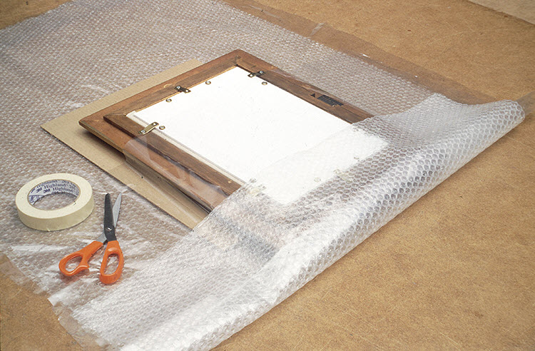
© Government of Canada, Canadian Conservation Institute. CCI 120554-0001
Figure 23. Framed painting positioned on cardboard and wrapped in Mylar or in polyethylene, then sealed with tape. A bubble pack layer may be added for basic cushioning.
2. Void filling
Void filling has several roles in packaging artwork. It can:
- provide physical reinforcement to help soft items retain their shape (Figure 24);
- prevent objects from turning inside packaging (for example, by stuffing the handle of a cup or vase with tissue paper);
- fill empty spaces around objects to prevent them from moving and colliding with each other;
- distribute impact forces over larger object surfaces; and
- improve cushion performance, for example, void fills added to foam pad designs (Figure 13).
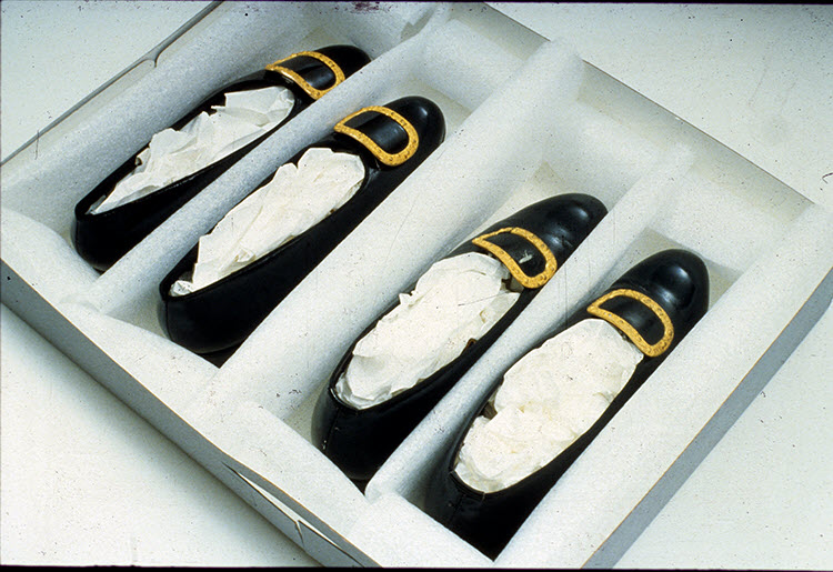
© Government of Canada, Canadian Conservation Institute. CCI 124703-0041
Figure 24. Void fills of tissue paper help items retain their shape.
3. Fitted mounts
Mounts can offer good protection on their own or they can be used as a foundation for additional protection. Mounts can be carved in blocks of foam or made with support ribs as in Figure 27.Endnote 58 Simple profile or contour gauges can be made to assist manual fabrication.Endnote 59 Consult the section Working with cushion materials for additional resources.
If using mounts to support small to medium-sized items in foam material, consider the following points.
- If the mount is intended to act as cushioning, refer to cushioning properties (consult the section Protective cushioning).
- Use chemically stable materials (such as polyethylene foam) for mount-making.
- Avoid less stable materials such as polyurethane foam, which may deteriorate and adhere to object surfaces. Wrap items if unstable mount materials must be used for short time frames.
- Always work within the proper load range for the mount material, with emphasis on the vertical direction, which is subject to constant gravity load (consult Table 7).
- Expect some movement between the object and mount. To reduce object movement or its effects on fragile surfaces:
- Increase the contact area between the mount and the object,
- Use a thin conforming interleave material to conform closely with object surfaces and
- Float a firm mount/object combination on soft protective cushions.
The mount in Figure 25 holds two pots and fits into a case that is cushioned (double case system). Note that:
- Pots are held down internally using firm foam inserts with a thin soft foam interleave at the ends. The fragile pot rims and handles float freely and do not bear loads in any direction.
- Base support ribs are covered with the same layer of thin foam.
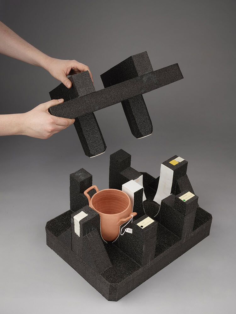
© Government of Canada, Canadian Conservation Institute. CCI 120714-0004
Figure 25. Fragile pottery on a carved polyethylene foam mount.
The unicorn in Figure 26 is a fragile, hollow form made of unfired clay. It has an open-ended hollow base and fragile projecting elements. Note that:
- Flat orientation is used to reduce stress on legs and the open cavity base, but since it is a medium-sized item, possible impact from all directions should still be anticipated.
- The bulk of the object mass (body) is firmly supported.
- The base is lightly supported so that it can follow any slight deflection of the body in the mount.
- Voids are carved around small projections (such as the horn, mane and points along tail) that are a small percentage of the total object mass. This will protect them from damage by forces that may deflect the object into the mount and when the object is placed inside or removed from the mount.
© Government of Canada, Canadian Conservation Institute. CCI 120714-0002
Figure 26. A hollow clay item with a complex shape and fragile projections is fitted into a carved polyethylene mount. (Consult the section Working with cushion materials.)
© Canadian Museum of History
Figure 27. A heavy, fragile argillite plate with an extensive network of internal flaws and cracks is evenly supported on a carved polyethylene mount and wooden fixture. (Consult the section Working with cushion materials.)
© Government of Canada, Canadian Conservation Institute. CCI 124848-0002
Figure 28. Large items with durable surfaces can be well protected with a cushioned mount in a large crate. Note that some movement can be expected between the object and mount.
Fitted mounts for large items
Large items can also be secured in fitted mounts. The back of the marble statue in Figure 29 is fitted to a contoured, high-density polyethylene foam sheet on a plywood back panel that is fastened to the steel frame. Padded straps secure the sculpture in place. Sculpture projections that are a small portion of the total object mass all float freely. The steel frame is stiff and resists deformation. It has been designed for reorientation and lifting by forklift and crane in a horizontal transit position. The lifting frame is an engineered structure and subject to quality checks for details such as weld quality during fabrication to ensure safety of the object and handlers.
© Government of Canada, Canadian Conservation Institute. CCI 80164-0357
Figure 29. Large marble statue (Queen Victoria, Library of Parliament) in steel moving frame.
4. Transit structures, frames and fixtures
Transit structures, to which objects are firmly fixed at strong attachment points, are usually used for durable items or as an intermediate treatment for fragile objects to be cushioned. Properly designed transit structures offer protection against distortion and help avoid handling impact or abrasion, but they offer little protection against shock or vibration. Placing a moving blanket or thin layer of foam between the transit structure and truck floor and sidewall can help absorb high-frequency vibration that may affect some fasteners, mechanical assemblies or fragile surface finishes during short trips. Consider cushioning the structure for fragile items or longer road journeys.
Points to consider:
- Ensure that the structure will not distort and impose strains on the contained item during routine handling or changes in position.
- Attach items at their strongest points using appropriate fastening methods. A soft, thin interleave material may be used to distribute loads and avoid abrasion at attachment points.
- The greater the number of attachment points, the lower the forces acting on each one (use multiple clips to secure a large painting in an HTS frame).
- Consider the object’s mass concentration and centre of gravity, and select support points carefully to enhance the protective ability of a structure.
- Objects can also be fixed to one common, stiff structural element (such as a base panel; Figure 33) to avoid strain caused by any deformation of the structure during handling, changes in position or responses to shock.
- A stiff structure can be simply cushioned with corner pads (Figure 37) while providing even support and distributing loads on the contained item.
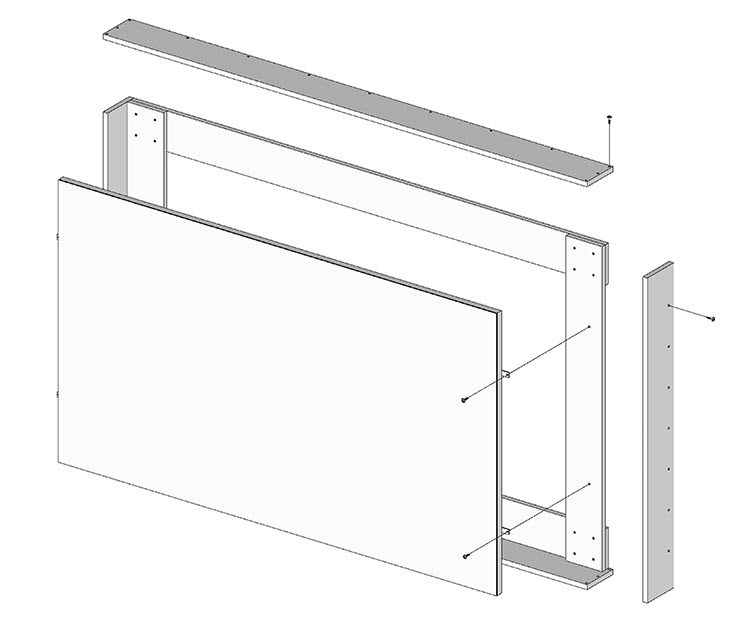
© Government of Canada, Canadian Conservation Institute. CCI 120714-0044
Figure 30. HTS frame developed by the National Gallery of Canada. HTS frames are simple structures that are often used for paintings; they are typically made from 19 mm (3/4 in.) plywood and assembled with glue and wood screws.
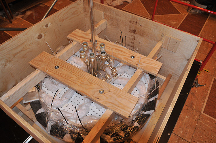
© Government of Canada, Canadian Conservation Institute. CCI 122650-0001
Figure 31. Deep HTS frame for large brass chandelier rings (West Block, Parliament Hill). The chandelier ring is durable and was transported manually in-house and transported locally by truck in the HTS frame alone.
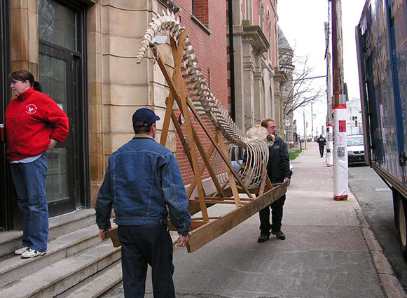
© Courtesy The Rooms Corporation of Newfoundland and Labrador and Randy Batten
Figure 32. Pothead whale skeleton being handled with a transit structure.
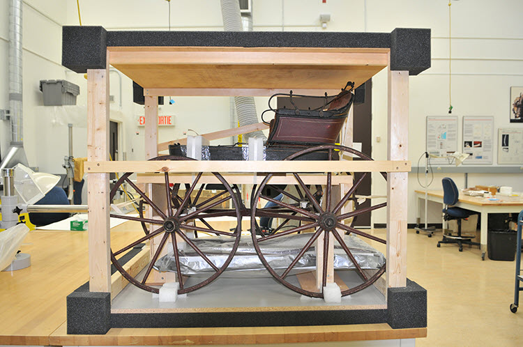
© Government of Canada, Canadian Conservation Institute. CCI 74463-0065
Figure 33. A buggy in a simple cushioned structure to be crated for return shipment by an art handler after conservation treatment. Because the structure is slightly flexible, attachments to secure the buggy are all made from the stiff base panel. Attachment points on the buggy are lightly padded.
5. Protective cushioning (suspension)
Suspension cushioning can be designed to provide a specific amount of shock protection on all sides of an object as well as vibration isolation. Suspension cushioning is most applicable for:
- small to medium package sizes that may be dropped from significant heights
- hazardous or undefined distribution channels
- moderately delicate to extremely fragile items
- objects of high value
- objects that require vibration isolation
Resilient foam, slings, springs and membranes can all be used as a suspension medium. Foam cushioning is a common choice for museum applications because it is economical, easy to obtain and work with, and highly effective when used correctly. Foam pads can be reused many times and switched between applications if they are not adhered to packaging. This is possible with encapsulation, corner pads and end cap designs, as noted in Table 19.
In order to obtain the best possible benefit from suspension cushioning, the cushioned item should be free of excessive looseness or vibration tendencies. The technical basis for this is discussed in Part 1, where practical measures are also described.
Typical pad layouts for four basic object shapes are shown in Table 19. Many other possibilities exist. Objects having these simple shapes and durable surfaces may be cushioned directly. Objects with irregular shapes, delicate surfaces or fragile projections may be secured in a mount or fixture to create simple shapes to which cushioning can be easily applied.
Details to consider for cushion layout include the following:
- Reasonable coverage on all sides (30% to 50% pad coverage).
- Symmetry; layouts that will deflect evenly on impact.
- Even weight distribution in the cushioned item.
Full coverage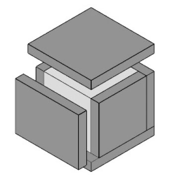
|
Full pad coverage offers physical protection and thermal insulation; most cushioning materials are also good insulators. Ensure that the fit is not too tight, as this will bind the object and reduce cushion effectiveness. Polyethylene wrap may help the item slide easily on the protective cushions. |
|---|---|
Corner pads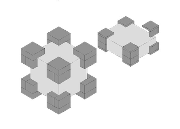
|
Corner pads offer very good protection with economical material use. |
End caps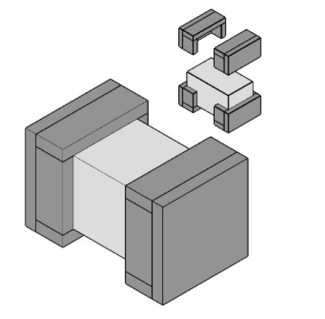
|
End caps can be single parts for small to medium-sized items. Two-part end caps allow easier access to the contents of heavy, top-loading inner cases without the need to lift the inner case out of the shipping container. |
Cushions for painting shapes
|
Small to medium-sized paintings with durable frames, transit frames or HTS frames can be floated on corner pads. Perimeter coverage may be increased with intermediate pads; full coverage may also be applied if the object is heavy. |
Note: The cushioned object can be an art object, an object/mount combination, a transit frame or framework or the inner case of a double case package. Many other pad layout possibilities exist.
Once the pad layout and coverage is determined, the appropriate material type and thickness can be selected (or verified) for the applicable drop hazard. Dynamic cushioning curves are used for this purpose, and design tools based on these curves are also available.Endnote 60 If the packer wishes to use a specific material, adjustments to the coverage may bring it into the required performance range. If this is not possible with reasonable coverage, another material may need to be considered.
Table 20 offers a quick application guide for two wrapping materials and several foam materials. The table identifies minimum thickness and load range combinations so as to limit shock in the delicate item category of 40 to 60 g’s for a 76 cm (30 in.) drop height.
| Material | Thickness: 50 mm (2 in.) |
Thickness: 76 mm (3 in.) |
Thickness: 100 mm (4 in.) |
|---|---|---|---|
| Air-encapsulated film (SD-240; large 12.7 mm [1/2 in.] bubbles) |
Exceeds 60 g's | 0.002–0.033 kg/cm2 (0.035–0.464 lb./sq. in.) |
0.002–0.033 kg/cm2 (0.035–0.464 lb./sq. in.) Consult note 2 |
| Cellulose wadding (recycled paper-based material) |
Exceeds 60 g's | 0.002–0.004 kg/cm2 (0.033–0.062 lb./sq. in.) |
0.002–0.009 kg/cm2 (0.033–0.126 lb./sq. in.) |
| Polyethylene foam (Ethafoam 220) 33 kg/m3 (2.0 lb./cu. ft.) |
0.025–0.050 kg/cm2 (0.356–0.717 lb./sq. in.) |
0.011–0.135 kg/cm2 (0.151–1.916 lb./sq. in.) |
0.008–0.124 kg/cm2 (0.115–1.769 lb./sq. in.) |
| Polyethylene foam (Ethafoam HS-45, 400) 64 kg/m3 (4.0 lb./cu. ft.) |
0.048–0.061 kg/cm2 (0.677–0.868 lb./sq. in.) |
0.020–0.131 kg/cm2 (0.289–1.867 lb./sq. in.) |
0.020–0.131 kg/cm2 (0.291–1.867 lb./sq. in.) |
| Chemically cross-linked polyethylene 33 kg/m3 (2.0 lb./cu. ft.) |
0.003–0.041 kg/cm2 (0.042–0.580 lb./sq. in.) |
0.013–0.123 kg/cm2 (0.188–1.800 lb./sq. in.) |
0.011–0.123 kg/cm2 (0.160–1.830 lb./sq. in.) |
| Polyurethane ester (“grey” open-cell foam) 24 kg/m3 (1.5 lb./cu. ft.) |
Exceeds 60 g's | 0.003–0.049 kg/cm2 (0.044–0.701 lb./sq. in.) |
0.002–0.080 kg/cm2 (0.029–1.140 lb./sq. in.) |
| Polyurethane ester (“grey” open-cell foam) 33 kg/m3 (2.0 lb./cu. ft.) |
0.006–0.039 kg/cm2 (0.079–0.550 lb./sq. in.) |
0.003–0.066 kg/cm2 (0.053–0.933 lb./sq. in.) |
0.004–0.102 kg/cm2 (0.050–1.453 lb./sq. in.) |
| Polyurethane ether (upholstery/packing foam) 24 kg/m3 (1.5 lb./cu. ft.) |
0.002–0.011 kg/cm2 (0.029–0.150 lb./sq. in.) |
0.002–0.012 kg/cm2 (0.029–0.229 lb./sq. in.) |
0.002–0.020 kg/cm2 (0.029–0.280 lb./sq. in.) |
| Polyurethane ether (upholstery/packing foam) 33 kg/m3 (2.0 lb./cu. ft.) |
0.002–0.016 kg/cm2 (0.032–0.227 lb./sq. in.) |
0.002–0.020 kg/cm2 (0.032–0.289 lb./sq. in.) |
0.002–0.030 kg/cm2 (0.032–0.440 lb./sq. in.) |
Notes:
- Data source: MIL-HDBK-304B.
- Load range as per 76 mm (3 in.) in the absence of data for 100 mm (4 in.).
For optimum cushion performance:
- Ensure that end caps or corner pads are made up of parts that are securely bonded together.
- Ensure that cushioning is not fitted so tightly as to bind the cushioned object in place.
- Wrap the object firmly in polyethylene wrap to help it move freely on its protective cushions while avoiding abrasion of its surfaces.
- Ensure that the packaging system can be put together and closed without the need to apply force.
- Avoid excessive looseness between the object and its cushioning.
- Make sure that object projections (if applicable) do not extend too far into the cushion sway space (the space between the cushioned object and the interior of the shipping case).
- Do not use the cushion sway space to store exhibit materials, hardware, tools or other items, because the cushioned object may need to deflect into this space on impact.
- Protection against low-level impact and vibration may be increased by slightly overloading the outer pad regions with taper cuts or ribs (consult endnote 28).
Working with cushion materials
Most foam cushioning material can be cut on a band saw, and individual pad components can be bonded together with hot-melt glue (be sure to provide adequate ventilation). For neat pad appearance, cushion assemblies can be trimmed on a band saw after having been glued together, but avoid trimming broad faces unless there is a need to reduce cushion thickness. Long salmon filleting knives, electric carving knives and utility knives are useful tools for cutting foam material. For additional information on materials, tools and how to work with foam materials and plastic, consult Technical Bulletin 14 Working with Polyethylene Foam and Fluted Plastic Sheet and Mount-making for Museum Objects.Endnote 61
6. Base cushioning
Large, heavy items may be adequately protected with base cushioning alone. This can help isolate items from vertical shock and vibration and help avoid the loosening of mechanical assemblies and fasteners.
An example of base cushioning for a piece of industrial equipment is shown in Figures 35a and 35b. Note the following:
- The equipment is secured to the platform with straps.
- Springs and straps absorb rebound and hold the equipment and base platform onto the skidded base.
When using base cushioning:
- Consider possible resonance effects.
- Provide features to absorb rebound.
- Ensure adequate stability if the object’s centre of gravity is high.
- Secure the item in the transport vehicle while still ensuring freedom of vertical movement.
- Ensure that the equipment item is held securely to the cushioned base and that restraint provisions are unlikely to loosen; items such as restraint straps may be duplicated for added security.
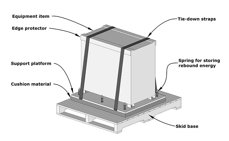
© Government of Canada, Canadian Conservation Institute. CCI 120714-0045
Figure 34. Base cushioning for objects such as large, heavy equipment items; use a protective cover or edge protectors at the top to protect the object from the sling loads. The cushioning material is bonded to the skid base and the underside of the support platform. The springs store rebound energy in this example.
7. Blocking, bracing, restraint
Blocking, bracing and restraint are used in large intermodal shipping containers and for securing fragile components in vulnerable objects or assemblies. A commercial example is the restraint hardware that is installed by washing machine manufacturers to secure and immobilize the spring mounted tub that the customer is instructed to remove on delivery. Another example is fixing a pendulum in a grandfather clock prior to moving.
Package dynamics
When applying protective measures, always consider dynamic effects. Understanding the dynamic behaviour of a package and its components is an important part of avoiding physical damage. For example, object movement on protective cushions is necessary to protect fragile items against shock and vibration, but movement in and among the parts of a package can be a problem if it happens in the wrong place, concentrates forces on vulnerable items or leads to secondary effects. The following considerations will allow for the best use of an investment in time, of packaging material and of quality transport services, while avoiding damage at low force levels that objects might otherwise tolerate without adverse effects.
- In objects: Flexibility, looseness and vibration tendencies in objects or their parts can be liabilities.Endnote 62 Identify object parts that are weakly held, loose or prone to vibration. Consider the following measures, if they can be carried out without introducing additional risk:
- disassembly (the vulnerability of individual parts may be less than the assembled whole),
- wrapping (to provide damping and gentle restraint),
- gentle restraint measures (tie downs, etc.),
- reinforcement (such as backing boards for canvas paintings),
- repair or strengthening of weak components (such as weak painting frames) and
- object treatments (adhesive facings, consolidation, canvas painting stretcher linings, etc.).
- Among objects: Multiple objects packaged together may collide, impose loads on each other or strike inner crate surfaces.
- Lightweight objects can be isolated from each other by wrapping and firmly packing the wrapped units.
- Small to medium-sized items can be isolated with mounts carved out of firm, chemically stable material such as polyethylene foam or padded dividers.
- Heavier items can be isolated from each other with durable partitions made of rigid foam, padded wood or other suitable materials.
- Avoid stacking art objects (with fragile frames) on top of each other, unless they can safely bear the weight of all units above. In Figure 37, the wood handling fixtures (not the foam mounts) bear stacking loads.
- Between objects and cushioning: Cushioned objects must deflect into cushion material without bending, or placing fragile surfaces or projecting elements at risk.
- Objects with simple shapes and flat, durable surfaces can be cushioned directly.
- Objects with moderately durable flat surfaces can be firmly wrapped in polyethylene to avoid abrasion (the inner surface of polyethylene will be locked by wrapping, and the outer surface will slide against the foam).
- Use a mount or fixture between the object and protective cushioning for complex or difficult items.
- Between objects and transit mounts: If an object is floated in a mount, some movement may be expected between the object surface and the mount. If there is concern about the effects this may have on a fragile surface or surface features:
- Achieve a firm fit between the object and mount, and float this combination on soft cushions.
- Attach the object to or secure it within a structure, and float it on protective cushions (this can eliminate effects on surfaces or projections if suitable attachment or support points can be found).
- Among cushioned items: If several items (such as inner cases) are floated on a common cushioning system in one shipping container, secure all of the units together (with straps, a fixture, inner case or other means) to avoid impact between the individual items (Figures 35a and 35b).
- Between a package and the transport vehicle: A package resting on the floor of a transport vehicle is capable of vibration and has one resonant frequency. Restraint alters this vibration tendency and raises its resonant frequency. Tie-down provisions do not need to be forceful to be effective, but they should be firm and unlikely to loosen.
- Among stacked items in the transport vehicle: Loosely stacked containers are capable of vibration and resonance. Stack resonance effects can increase loads on the lower containers.
Double case packaging
Double case packaging combines several of the above methods and can provide high protection for difficult items with fragile surfaces, existing damage, fragile projections and odd shapes. It has been used to ship highly fragile contemporary art items, marble portrait busts, argillite works and others.
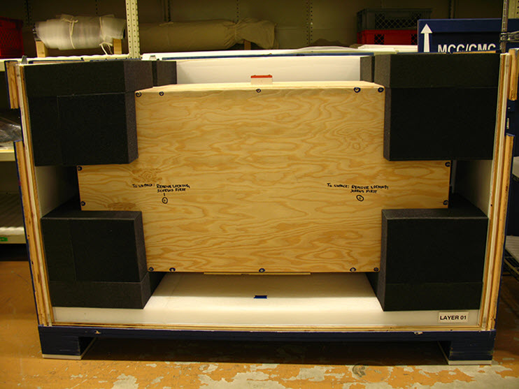
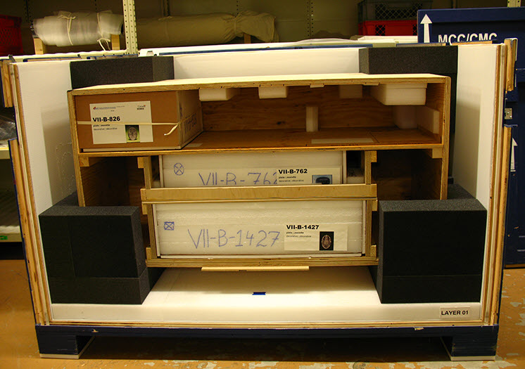
The cushioned “object” in a double case system is the inner crate, mount or fixture. This object may contain one or several items, and it can be densely packed with care to ensure good support and restraint while avoiding collision or adverse effects (consult the section Package dynamics). Once a double case system is constructed, it can be reused many times. A practical guide on fabricating corner pad cushions for double case systems is availableEndnote 63.
The advantages of a double case system are as follows:
- The inner case can offer a second line of defence against puncture.
- Deformation of the exterior case will not deform the cushioned item inside.
- Multiple items can be closely packed inside the inner case.
- Many objects can be protected with one cushioning system.
- The inner case can be removed from the shipping crate and transported more easily through narrow access routes while still protecting the object inside.
- Double cases can be constructed with cubic shapes for optimum thermal buffering.
- A densely packed inner case will increase heat capacity and improve thermal buffering.
- Insulation can be applied to the inner case interior for impact protection and improved thermal buffering.
- The inner case can be used for long-term storage.
- The inner case may be shipped on its own for short, controlled journeys depending on the packing treatment, shipping risk profile and object fragility.
- An existing package with limited cushioning can be converted to a high-protection package for limited use by using a triwall cardboard exterior case and corner pads (Figure 37).
- The double case system reduces demands on the exterior crate as a barrier against agents such as water, pests, puncture and others.
- The enclosed air space and limited contact between the object (inner crate) and the shipping case walls improve thermal insulating ability.
Shipping containers
The shipping container is the first line of defence against impacts, punctures, dents, abrasion and environmental agents. Shipping containers range from simple corrugated containers to large steel shipping containers used for international shipment.
Corrugated containers
Corrugated containers have been used for local moves and source-to-destination transport in low-hazard (art handler) networks. They are lightweight and inexpensive, and they can be reused or recycled. Corrugated container options include simple cardboard boxes, mirror boxes (for paintings) and durable triwall cardboard containers capable of carrying substantial loads. Triwall containers have been used as both exterior containers and as inner cases of double case packages (CCI Note 1/4 Making Triwall Containers).Endnote 64
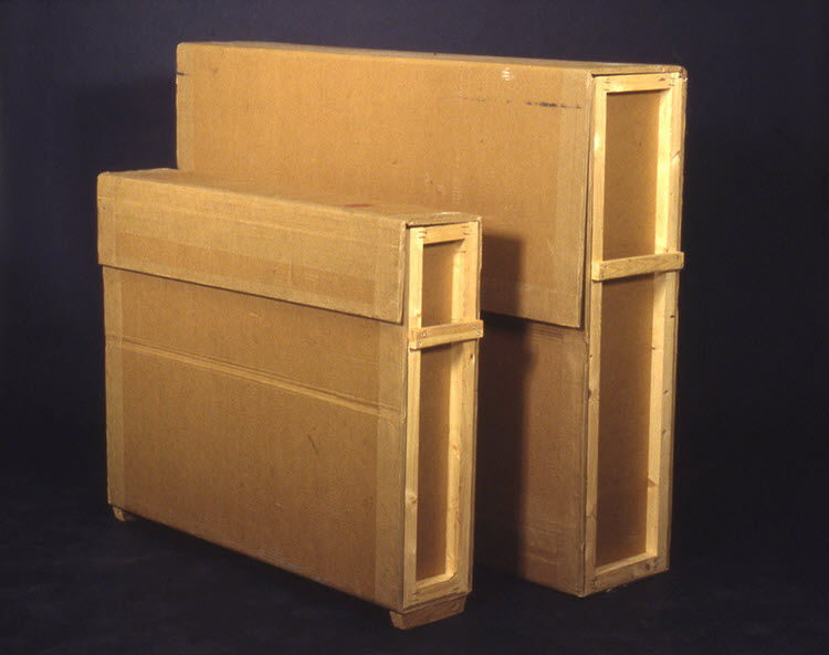
© Government of Canada, Canadian Conservation Institute. CCI 120714-0063
Figure 36. Strong, inexpensive and easily fabricated containers made of highly durable triwall corrugated material (CCI Note 1/4 Making Triwall Containers).
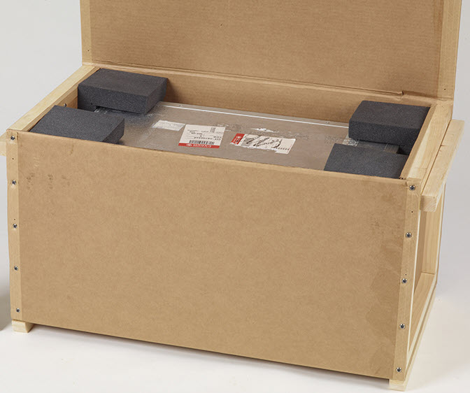
© Government of Canada, Canadian Conservation Institute. CCI 98010-0062
Figure 37. Corrugated containers make it easy to add extra protective cushioning to an existing package. The original road case inside still provides a durable barrier against puncture. This approach was used to return the interior package containing an object in a firm carved mount to a client on a one-way return shipment to Canada’s far north. The corner pads are the same as the pads shown in Figure 12.
If corrugated containers are used, their limitations should be kept in mind, such as higher susceptibility to puncture, crushing and deformation. Corrugated materials may be adversely affected by water and high humidity. Sustained high humidity can reduce the strength of some corrugated materials by 50% or more. Open cardboard flutes may also provide a harbour for insect pests. The flutes on the triwall crate material in Figures 36 and 37 have been covered with reinforced, self-adhesive kraft tape.
Corrugated sheet material consists of fluting bonded to paper facing (Figure 38). Fluting can be made of recycled paper or other material and may include starch-based adhesives or polymeric adhesives that perform better in damp conditions. The most common flute sizes for corrugated material used for shipping containers are A, B and C.
- A FLUTE – 4.7 mm (3/16 in.): Good stacking and cushioning/protection
- B FLUTE – 3 mm (1/8 in.): Good puncture resistance, most common grade
- C FLUTE – 4 mm (5/32 in.): Good stacking and cushioning/protection, very common grade
The facing can be made of various papers (kraft paper and others) of different weights. Water-resistant adhesives can also be used with corrugated material treated with wax or by other means for applications involving high moisture or possible contact with water.
Corrugated material comes in several forms: single-face (one sheet of facing paper), single-wall (two facing sheets), double-wall (three facing sheets) and triple-wall (four facing sheets). Single-face corrugated cardboard is used for protective wrapping and basic cushioning as a flexible primary packaging material and can be used to form pads and tubes. Single-wall cardboard is the most commonly used form in industrial applications. It is used for containers and inner partitions for boxes. Double-wall cardboard offers additional strength and rigidity when required. It is used to make containers for bulky products such as machinery appliances, dinnerware and furniture. Triple-wall cardboard offers high strength for large, heavy items and for making very durable containers. It is used as a wood substitute for bulk bins and boxes. Multi-wall corrugated material may consist of one or several flute types.
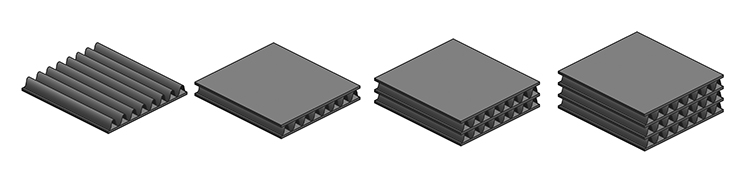
© Government of Canada, Canadian Conservation Institute. CC 120714-0047
Figure 38. Structure of corrugated materials: single-face, single-wall, double-wall and triple-wall.
Common cardboard strength designations apply in situations where corrugated containers are stacked and palletized. Strength guidelines for the shipment of individual boxes through express delivery networks are now becoming available. Note that the protection offered by a cardboard box will decrease with use. If cardboard boxes are reused, ensure that they are in good condition and free of tears, punctures, corner damage or torn flaps.
Road cases (ATA cases, flight cases, roadie cases, transit cases)
Road cases are durable, lightweight containers made of plywood laminates and held together with riveted attachments to aluminum extrusions. They were originally developed by airline packaging engineers in the early 1960s. Road cases can be made to any required size, and local fabricators can be found in most major cities. The case panels are plastic or plywood covered with either ABS or aluminum, with the most common thickness values being 6.35 mm and 12.7 mm (1/4 in. and 1/2 in.). The cases come in two ATA categories: Category 1 standard cases are reusable for at least 100 round trips, and Category 2 cases, for 10 trips.
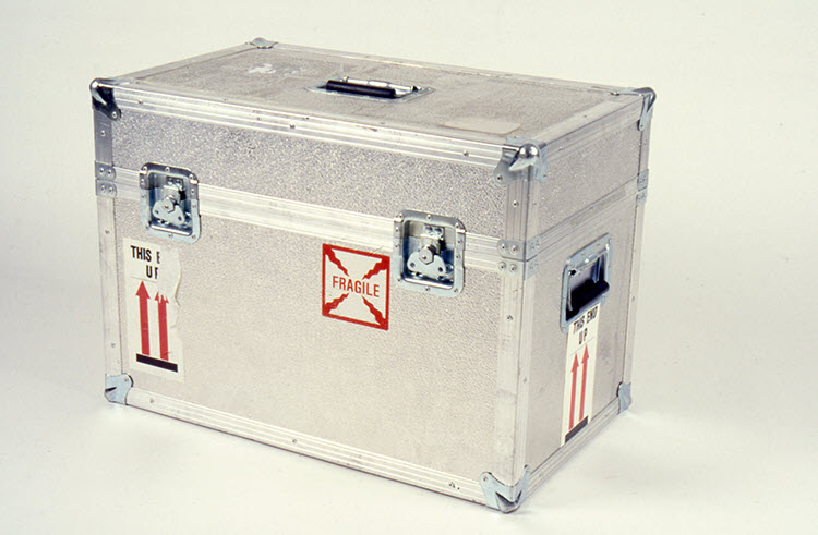
© Government of Canada, Canadian Conservation Institute. CCI 120714-0048
Figure 39. Road case with aluminum/plywood laminate panels held together with riveted aluminum extrusions. This case also includes durable ball corners, recessed handles and draw latches.
Road cases can be used on their own as shipping containers or as the interior cases for double case package systems. A wide range of hardware and accessories is available for customizing road cases, such as various closure options, interior partitioning, wheels, retracting handles and durable ball corners.
Plastic and aluminum cases that meet ATA categories are also available. Plastic cases are highly resistant to moisture and chemicals. The newer plastic container materials are greatly improved over earlier materials, such as fibreglass, that were susceptible to fracture at low temperature. They also have a low WVTR and effective seals against water. Aluminum cases come in various sizes, and some manufacturers can fabricate these cases to specific size requirements. Very large aluminum cases have been used as an alternative to wood crates for large items to reduce package weight, but at considerable expense.
Wooden crates
Wooden crates offer excellent protection for valuable items and are a popular choice for museum packing. They can be constructed to almost any size with common workshop tools and equipment, and a well-constructed wooden crate can be reused many times.
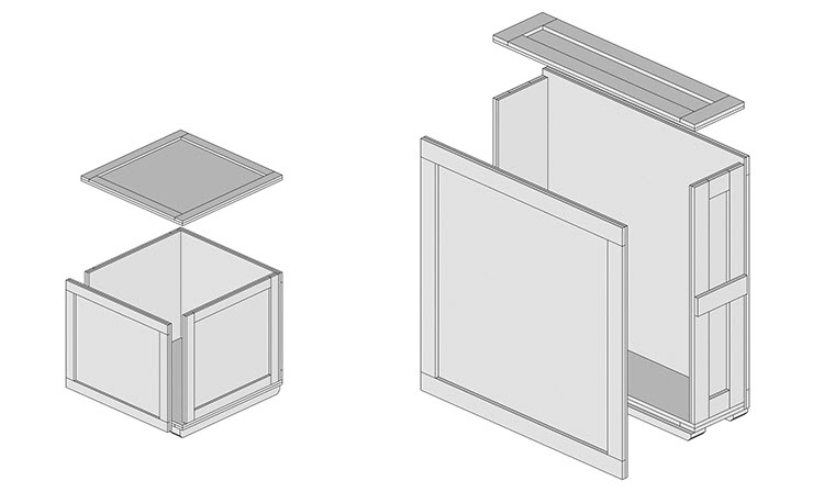
© Government of Canada, Canadian Conservation Institute. CCI 120714-0050
Figure 40. Typical crates for domestic and overseas shipment with rub strips and handles added to a standard design, such as ASTM D6251.
Published standards for crate construction can help guide woodworkers if the crating task is new to them. Having a crate conform to a standard design (or equivalent) can be helpful in the event of a damage claim. Further to specifications found in standards, museum crates will include special features described below (consult the section Features of good crating).
Many organizations have developed successful designs of their own and have refined them over years of use. It is not unusual for such designs to share common features with one or more of the existing crating standards.
Crating standards are published by organizations such as ASTM and the military. Some of these crating standards can also be found online.Endnote 65 Publications by commercial organizations such as the Engineered Wood Association provide construction details summarized in chart form.Endnote 66 Computer software for building standard crates is also available (Crate Pro).Endnote 67 An example of a crate construction standard for domestic and overseas shipment of commercial goods is ASTM D6251, which is well-suited to many museum applications.
| Category | Standards |
|---|---|
| Light-duty (up to 454 kg [1000 lb.]) |
ASTM D6251 PPP-B-601 |
| Medium-duty (up to 1134 kg [2500 lb.]) |
ASTM D6256 MIL-B-26195 |
| Heavy-duty (up to 13,608 kg [30,000 lb.]) |
ASTM D7478 MIL-C-104 |
Plywood is commonly used for crate construction. Although 12.5 mm (1/2 in.) is the preferred minimum for many museum applications, the thinnest available option offers good protection, as confirmed by the following points for 9.53 mm (3/8 in.):Endnote 68
- Superior to lumber crates built of 19 mm (1 in. nominal) thick boards.
- Resistant to a sandbag drop from 1.5 m (5 ft.) (Figure 19).
- Able to sustain fork tine impacts of 13 km/h (8 mph) near crate edges, where the plywood panel meets the framing. More force is required to puncture the panel as the impact point shifts away from the edge.
- A good barrier against moisture.
Some museums have in-house crating facilities. Others have cases made by outside suppliers who may guarantee containment and packing quality, which can be helpful in the event of a claim. In commercial shipping, crates made to standard specifications can also lower insurance rates.
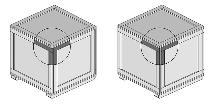
© Government of Canada, Canadian Conservation Institute. CCI 120714-0051
Figure 41. Crate framing for stiffness (left) and stacking strength (right).
Features of good crating
Features of good crating include the following:
- Handholds are located so as to help minimize drop heights. Knee height is a good general guide for larger packages when manual handling is anticipated.
- Recessed hardware (such as latches) that will not get knocked off or damaged during shipment, or spacers to protect protruding hardware.
- Clear and permanent labelling (waterproof glue and ink) with characters at least 8 mm (0.3 in.) high or more. Place labels on opposite sides.
- Discreet labelling (fragile, handle with care, etc.) of contents and contact information of the party that will receive the shipment. This may help avoid the need to open the package for inspection. Labels that specify “crates—contain artwork” may raise authority’s suspicion about the contents.
- Strong panels. Crate panels of 12.5 mm (1/2 in.) or more can be used for domestic or overseas shipment. Commercial standards may specify thinner panels (9.5 mm [3/8 in.]), but 12.5 mm plywood is flatter and easier to work with, and the cost difference between the two is small.
- Strong base. Use 19 mm (3/4 in.) plywood for the crate base panel.
- Reinforcing battens at 60 cm (24 in.) intervals on wider crate panels.
- Waterproof glue used for assembly.
- Proper selection of interior finishes (consult the section Exterior and interior paint for wood crates).
- Framing details that shed water from the top panel (a gap between several top panel framing members or a drainage hole, as specified in ASTM 6251).
- Framing for torque strength or stacking, as required (Figure 41).
- Access for handling equipment, such as a pallet truck (Figure 42).
- Appropriate interior coatings to limit moisture transmission or pollutant off-gassing.
- Effective sealing against agents of deterioration, such as water, contaminants and pests (discussed in further detail below).
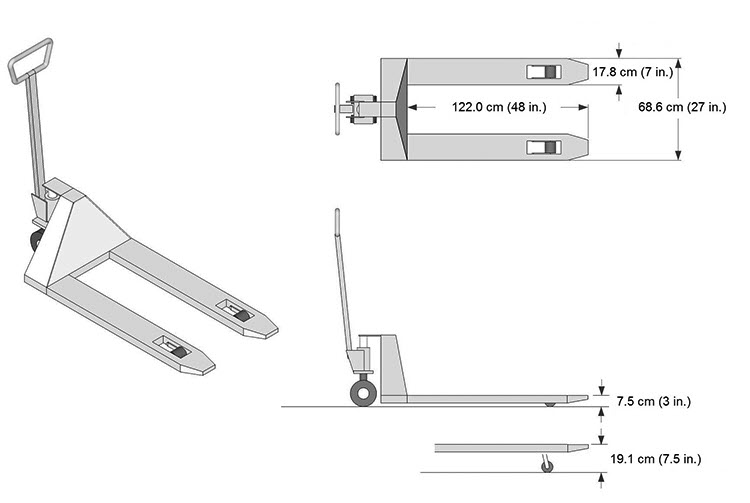
© Government of Canada, Canadian Conservation Institute. CCI 120714-0052
Figure 42. Common pallet truck dimensions.
Closures for wooden crates
Three commonly used closures are draw latches, link plates and screws (Figure 43). Washer-head screws pull down crate lids securely. Draw latches and closure plates are a good choice for repeated opening and closure, as they avoid the loss of strength of screw fastening in wood with repeated use.
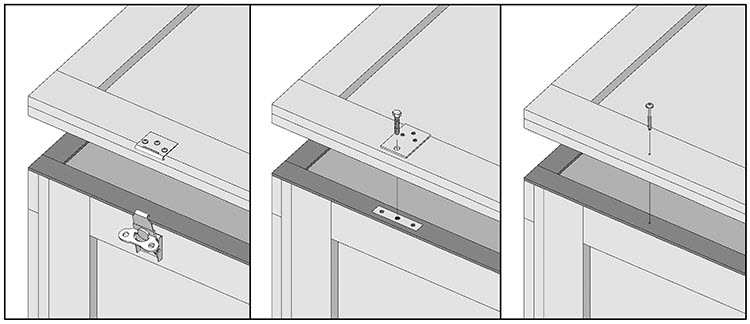
© Government of Canada, Canadian Conservation Institute. CCI 120714-0054
Figure 43. Common crate closure hardware. Draw latch (left), closure plates (middle) and washer head screw (right).
Knock-down crating
Knock-down crating can mean two things:
- crating that is shipped in a knocked-down (flat) package for final assembly by the customer; or
- crating equipped with specialized fastener systems that can be assembled, used and then disassembled and conveniently stored in a space that occupies a small percentage of its assembled volume (about 20%).
The hardware for commercial knock-down wood crating systems is offered by companies such as Hardy-Built Systems, Nefab and Klimp Industries.Endnote 69 A knock-down crating concept developed at CCI for the shipment of paintings through low-hazard networks is shown in Figures 44a to 44d. It has been used on numerous occasions to return items to clients after treatment using high-quality source-to-destination art handler truck transport with door-to-door oversight. The only packaging cost to the client is that associated with the HTS frame (which can be retained for storage or future use) and corrugated cover panels, as well as the cost of returning reusable crate components (channel frame sections and corner pads) by common carriers.
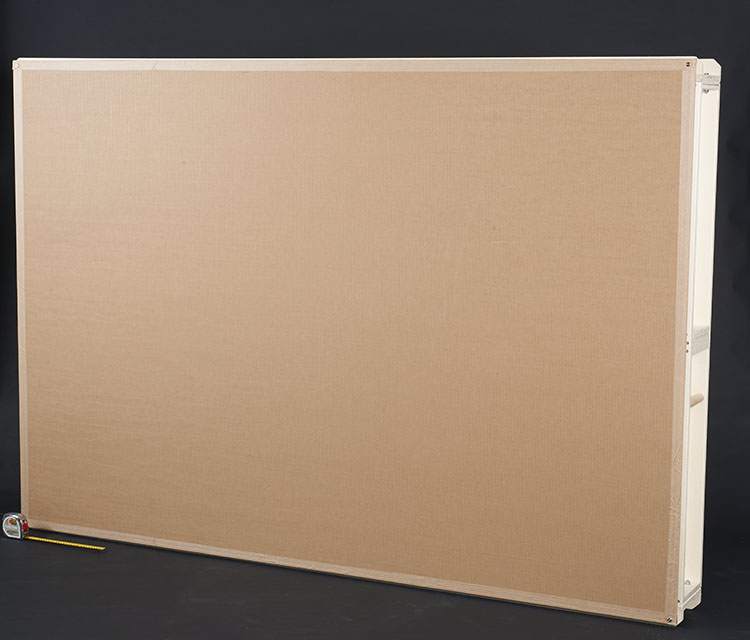
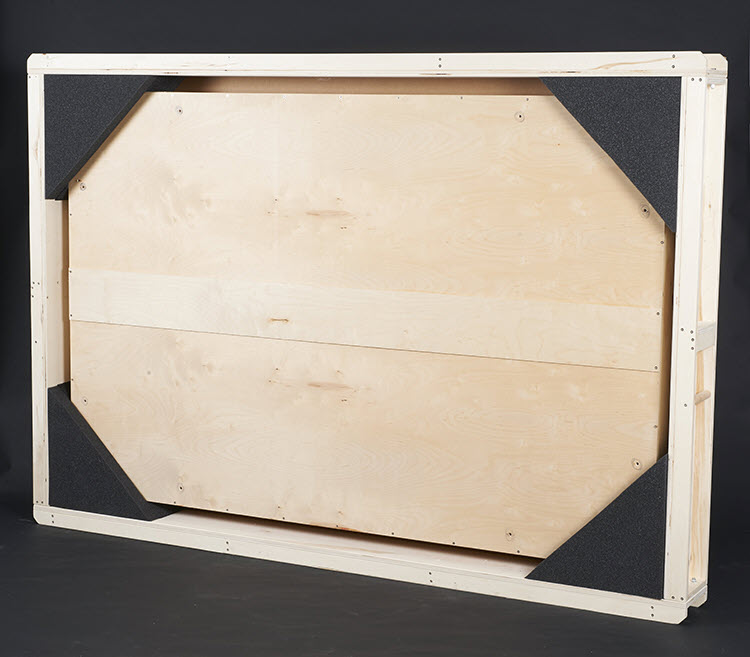
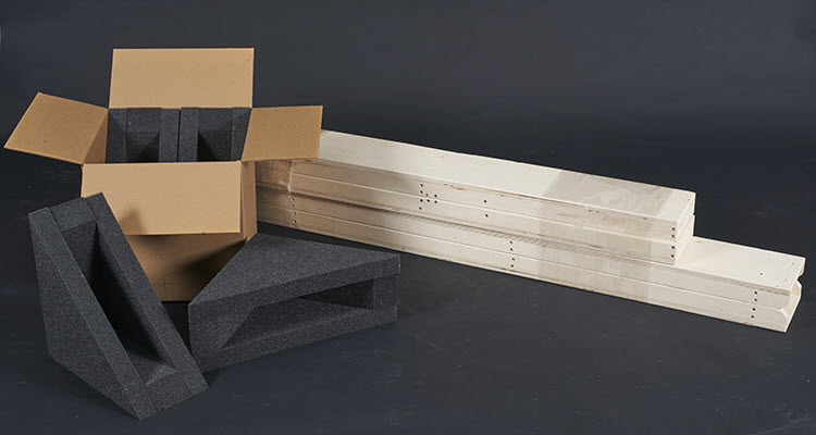
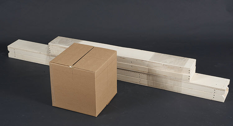
Lightweight crating precautions
Lightweight crating may be considered for controlled transportation networks, but there should be an assurance of full oversight by a high-quality carrier, as in a door-to-door art handler scenario, as well as an understanding of the limitations of such packaging. If not, shipping items in lightly constructed cases may increase the risk of damage even for simple source-to-destination shipments.
Exterior and interior paint for wood crates
A painted crate exterior can help identify cargo in a crowded warehouse. A fresh coat of paint can also provide indications of rough handling and can alert the recipient to quickly inspect the contents of a package for possible damage on delivery. Exterior paint also limits the rate of moisture permeation through crate walls.
The choice of exterior paint is not critical, and the packer is free to choose any paint for this purpose. Some crate builders prefer clear coat finishes in order to ensure that heat treatment stamps remain visible (consult the section International standards for phytosanitary measures).
The case interior may be left uncovered or unpainted if the contents are wrapped or if they are not to be stored in the case for long periods of time. Applying a coating to the interior crate surfaces may be beneficial if:
- there is a possibility of long-term storage,
- crates are to be stored in uncontrolled environments,
- the contents are not wrapped or
- the contents are highly susceptible (e.g. silver, lead, etc.) to compounds that may be released from wood packaging material.
The following paints are suitable as interior finishes:Endnote 70
- Acrylic emulsion (latex) paint
- Acrylic–urethane emulsion paint
- Two-part epoxy or two-part polyurethane
Note that these paints will need to dry thoroughly (four weeks is recommended) before the case is used.
Some paints and coatings should never be used inside shipping crates, as they give off compounds that could react with object materials. Avoid using any coatings formed by oxidative polymerization such as:
- oil-based paint
- alkyd
- one-part epoxy
- oil-modified polyurethane
International standards for phytosanitary measures
International phytosanitary standards and regulations are applicable to both wood packaging material and package contents. The ISPM 15 standard is summarized here, but the reader should consult the standard itself for detailed information.Endnote 71 The reader is also advised to consult the Canadian Food Inspection Agency (CFIA) for the most current requirements and applicable categories of museum objects and artwork.Endnote 72
Wood packaging material used for international shipment is subject to regulation, as outlined in the ISPM 15 standard. This standard was issued by the International Plant Protection Convention (IPPC) to harmonize the import regulations of countries around the world so as to avoid the introduction and spread of harmful insects. In Canada, the IPPC program is administered by the Plant Biosecurity and Forestry Division of CFIA. The Government of Canada, by the authority of CFIA, requires that all solid wood products entering Canada be IPPC-certified.
The ISPM 15 applies to all solid wood packaging that is thicker than 6 mm (0.24 in.) and shipped between countries. This includes crates, crate components (skids, framing, etc.), pallets and even dunnage (material used inside packages for blocking, bracing or other purposes, such as HTS frames).
There are three ways that the packer can satisfy the ISPM 15 requirements.
- Use wood products that are not subject to regulation. This includes wood-based products, such as plywood, particleboard, oriented strand board or veneer, that are manufactured using glue, heat and pressure, or a combination thereof, and that are considered sufficiently processed to eliminate the risk associated with raw wood.
- Purchase crates from a facility that is certified by the Canadian Wood Packaging Certification Program.
- Heat-treat and stamp existing crates made of materials that are subject to regulation. Once the crates are heat-treated and carry a heat treatment stamp (Figure 45), they can be used indefinitely without the need for any further heat treatment, unless they are repaired or remanufactured (consult ISPM 15 for details).
Wood packaging that meets the ISPM 15 requirements carries permanent markings that are legible and visible when the package is in use. A typical marking is shown in Figure 45. It consists of the IPPC symbol on the left, an ISO country code followed by the national plant protection organization (NPPO) responsible for ensuring appropriate wood use (CFIA in Canada) and the treatment method, such as HT 56/30 (heat treatment, 56°C core temperature, 30 minutes), MB (methyl bromide) or DH (dielectric heating). Cases may be finished with clear coatings to avoid hiding these marks.
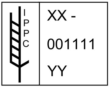
![]() Public domain
Public domain
Figure 45. A heat treatment stamp, including the country code (XX), the producer or treatment provider code (a series of digits and letters which are assigned by the NPPO to each company) and the treatment code (YY).
Package performance
Simple drop tests of crates containing simulated loads onto a concrete floor can provide valuable information on case integrity and performance, especially for non-standard designs. Detailed performance testing procedures for packages are described in standards such as ASTM D4169.Endnote 73 The thermal half-times of actual packaging systems can be measured with very simple tests and basic equipment, if accurate performance data is required.Endnote 74
Shipping indicators and loggers
There are many shock and vibration indicators and loggers on the market. Some also allow for the logging of temperature, humidity and pressure. They can:
- provide a record of when or where significant and possibly damaging events may have taken place during shipment,
- provide information on a distribution network to help refine package design and
- gather data when testing the performance of a package.
Indicators
Indicators are simple, inexpensive devices that provide evidence of temperature extremes, freezing events, humidity extremes, position changes (tilt), shock in excess of specific limits and other factors. The major limitation of an indicator is that it does not provide a time record of activation. Several shock indicators now include a simple countdown timer that is started at the beginning of a journey and will stop when a pre-determined shock level (25 g or 50 g, depending on the model) is first exceeded. Since significant events are infrequent, this offers the possibility of capturing the time of a damage-causing event.
Event recorders
Event loggers improve on indicators and have the ability to record time-stamped values for shock, temperature, humidity or other quantities within user-defined time intervals. Inexpensive shock event recorders record shock in one direction (uniaxial) or three (triaxial). These recorders and their software (where applicable) are often user-friendly.
Waveform recorders
Waveform recorders capture a time history of quantities such as shock and vibration. This data may be captured in one direction or axis (uniaxial) or all three (triaxial). Analysis software can be used to determine the cause of impact events and their damage potential. Some software tools can also recreate a visual representation of the package trajectory that caused an impact event. The recorders can also be coordinated with GPS data to provide information on the journey such as vehicle location, speed and stopovers. These devices and their software are more specialized and intended for users with some background in vibration concepts, terms, quantities and measurement.
Temperature and humidity loggers
There are many commercial logger choices for acquiring temperature and humidity data. Note that when monitoring RH, a logger placed in the volume of air surrounding a packed object (headspace) may show large RH swings. For an initial headspace condition of 20°C (68°F) and 50% RH, a 5°C (9°F) temperature increase or drop will change the humidity from 50% to 37% or 68% RH, whichever the case may be. If the moisture barrier is effective and sufficient hygroscopic material is enclosed, the RH level will return to a value that is near the initial value with very little moisture transfer between the enclosed air volume and the object.
Conclusion
Priority concerns for shipping are physical hazards, keeping track of objects or their parts and environmental influences. While physical hazards during shipment are important to address, shipping-related activities such as packing, unpacking as well as exhibit installation and removal may also introduce significant hazards that may be partially addressed with well-designed packaging concepts.
For shipment, it is important to consider how objects and package components interact to ensure that package durability is matched to the chosen distribution environment and that packaging can adequately limit foreseeable hazards. For valuable items considered suitable for travel, the demands on packaging will be reduced and the margin of safety increased by limiting unnecessary hazard exposure through carrier selection and planning, which offer significant benefits in light of the uncertainty of object vulnerability and limited opportunity to verify the performance of museum packaging.
No matter which transport network is chosen, a certain degree of hazard exposure is inevitable. While it is important to consider and limit individual hazards such as shock, the information on which to base an exact cushioning requirement is often unknown or approximate, and this is only one part of protecting artwork from physical damage. The dynamic features discussed here will help make the best use of an investment in quality transport and packaging for fragile items and more durable ones alike. When formulating packing concepts, a broad consideration of all applicable agents will help in the design of an effective system to counteract their combined effects; moreover, in practice, individual control features may offer multiple benefits.
With careful attention to fundamental issues such as primary packing and dynamic interactions, packaging resources can be used to great advantage. For museum applications, primary packing is an important means of addressing uncertain or hidden object vulnerability and increasing object durability for shipment. Many environmental agents can be controlled at this level of packaging. The packaging field then offers useful information on hazard estimation, design methods and package material performance that can be readily transferred to art shipments. Performance targets for art items are suggested here, as well as control measures to minimize hazard exposure.
While there are limits as to what can be safely shipped in affordable packaging, the various packaging options discussed here can help reduce risks across a wide range of applications. Museums using controlled transport networks may achieve a wide margin of safety with hazard intensities limited to levels that are well below object damage thresholds in cost-effective packaging. Very high levels of protection can be provided for unusually fragile items with specialized designs, when called for. Artists who use higher hazard commercial shipping networks may apply the principles described here in economical ways, starting at the object design stage through to packaging, to substantially increase their assurance of safe shipment.
Acknowledgements
The author wishes to thank his colleagues at CCI, across Canada and internationally for their collaboration on packaging-related projects over the years. The author also wishes to thank clients in cultural organizations, artists, packing workshop participants, art handlers, students in conservation programs and others whose projects, enquiries and interest have helped further CCI’s research in this area and develop a base of knowledge and experience to share with the cultural community.
Bibliography
Allen, D.C. “Maximum Drops Experienced by Packages in Transit.” Journal of the Society of Environmental Engineers 53 (1972), pp. 21–28.
American Society for Testing and Materials. “ASTM D4169-91a: Standard Practice for Performance Testing of Shipping Containers and Systems.” In Annual Book of ASTM Standards, vol.15.09. Philadelphia, PA: American Society for Testing and Materials, 2005.
American Society for Testing and Materials. “ASTM D6251: Standard Specification for Wood-Cleated Panelboard Shipping Boxes.” In Annual Book of ASTM Standards, vol. 15.10. Philadelphia, PA: American Society for Testing and Materials, 2007.
American Society for Testing and Materials. “ASTM D7478: Standard Specification for Heavy Duty Sheathed Wood Crates.” In Annual Book of ASTM Standards, vol. 15.10. Philadelphia, PA: American Society for Testing and Materials, 2008.
American Society for Testing and Materials. “ASTM D6256: Standard Specification for Wood-Cleated Shipping Boxes with Skidded, Load-Bearing Bases.” In Annual Book of ASTM Standards, vol. 15.10. Philadelphia, PA: American Society for Testing and Materials, 2010.
American Society for Testing and Materials. “ASTM E72-15: Standard Test Methods of Conducting Strength Tests of Panels for Building Construction.” In Annual Book of ASTM Standards, vol. 04.11. Philadelphia, PA: American Society for Testing and Materials, 2015.
Andreason, K.R. Plywood Crate Tests, American Plywood Association Laboratory Report 111, Applied Research Department, Technical Services Division. Washington, D.C.: American Plywood Association, 1968.
Australian Government Department of Health and Ageing. National Vaccine Storage Guidelines. Canberra, Australia: Commonwealth of Australia, 2005.
Bakker M, ed. The Wiley Encyclopaedia of Packaging Technology. Chichester, UK: John Wiley & Sons, 1986.
Barclay, R.L., A. Bergeron and C. Dignard. Mount-making for Museum Objects, 2nd ed. Ottawa, ON: Canadian Conservation Institute, 2002.
Brandenburg, R.K. and J.J. Lee. Fundamentals of Packaging Dynamics. Itasca, IL: L.A.B. Equipment, Inc. 2001.
Broch, J.T., ed. Mechanical Vibration and Shock Measurements. Nærun, Denmark: Bruel & Kjaer, 1980.
Choi, S.J. and G. Burgess. “Practical Mathematical Model to Predict the Performance of Insulating Packages.” Packaging Technology and Science 20,6 (2007), pp. 369–380.
Department of Foreign Affairs and International Trade. Export Packaging: A Guide for Exporters. 3rd ed. Ottawa, ON: Mariport Group Ltd., 2000.
Department of Foreign Affairs and International Trade. Safe Storage: A Guide for Exporters, 2nd ed. Ottawa, ON: Mariport Group Ltd., 2000.
DOW Chemical Company. Product and Design Data for Ethafoam Brand Polyethylene Foam. Technical Publication 172-1151-85. Midland, MI: Dow Chemical Company, 1985.
Foley, J.T. Transportation Shock and Vibration Descriptions for Package Designers. Albuquerque, NM: Sandia Laboratories, 1972.
Forest Products Laboratory. Wood Handbook—Wood as an Engineering Material. General Technical Report FPL-GTR-190. Madison, WI: U.S. Department of Agriculture, Forest Service, Forest Products Laboratory, 2010.
Glass, S.V., S.L. Zelinka and J.A. Johnson. Investigation of Historic Equilibrium Moisture Content Data from the Forest Products Laboratory. General Technical Report, FPL-GTR-229. Madison, WI: U.S. Department of Agriculture, Forest Service, Forest Products Laboratory, 2014.
Gottlieb, H.P.W. “The Effect of an Enclosed Air Cavity on a Rectangular Drum.” Journal of the Australian Mathematical Society, Series B/24 (1983), pp. 343–349.
Harris, C.M. Shock and Vibration Handbook, 3rd ed. New York, NY: McGraw-Hill Book Company, 1988.
International Plant Protection Convention. International Standards for Phytosanitary Measures: ISPM 15, Regulation of Wood Packaging Material in International Trade. Rome, Italy: Food and Agriculture Organization of the United Nations, 2009.
Leinberger, D.A. Temperature and Humidity in Ocean Containers. Paper presented at the Dimensions.06 Conference of the International Safe Transit Association, Institute of Packaging Professionals, February 27, 2006.
Marcon, P. Six Steps to Safe Shipment. Ottawa, ON: Canadian Conservation Institute, 2011.
Marcon, P. Foam Corner Pads. CCI Notes 20/2. Ottawa, ON: Canadian Conservation Institute, 2020.
Marcon, P. and T.J. K. Strang. PadCAD Cushion Design Software. Ottawa, ON: Canadian Conservation Institute, 1999.
Marcon, P., D. Couture-Rigert, M. Harrington and P. Heinrichs. “Packing and Transport of Hollow Plaster Sculpture,” In ICOM Committee for Conservation, 12th Triennial Meeting, Lyon, France, 29 August – 3 September 1999: Preprints, vol.1. London, U.K.: James & James, 1999, pp. 77–82.
Mecklenburg, M.F. ed. Art in Transit: Studies in the Transport of Paintings. Washington, D.C.: National Gallery of Art, 1991.
Mecklenburg, M.F. Determining the Acceptable Ranges of Relative Humidity and Temperature in Museums and Galleries, Part 1, Structural Response to Relative Humidity. [N.p.]: Smithsonian Museum Conservation Institute, 2007.
Mecklenburg, M.F. Determining the Acceptable Ranges of Relative Humidity and Temperature in Museums and Galleries, Part 2, Structural Response to Temperature. [N.p.]: Smithsonian Museum Conservation Institute, 2007.
Mecklenburg, M.F. and M. Richard. Art in Transit: Handbook for Packing and Transporting Paintings. Washington, D.C.: National Gallery of Art, 1991.
Mecklenburg, M.F. and C.F. Tumosa. “An Introduction into the Mechanical Behavior of Paintings under Rapid Loading Conditions.” In M.F. Mecklenburg, ed., Art in Transit: Studies in the Transport of Paintings. Washington, D.C.: National Gallery of Art, 1991, pp. 137–172.
Michalski, S. “Leakage Prediction for Buildings, Cases, Bags and Bottles.” Studies in Conservation 39,3 (1994), pp. 169–186.
Michalski, S. and P. Marcon. “Mechanical Risks to Large Paintings Such as Guernica During Transit.” In El Guernica y los problemas éticos y técnicos de la manipulación de obras de arte. Santander, Spain: Fundación Marcelino Botín, 2002, pp. 87–98.
Moureh, J., O. Laguerre, D. Flick and B. Commere. “Analysis of Use of Insulating Pallet Covers for Shipping Heat-sensitive Foodstuffs in Ambient Conditions.” Computers and Electronics in Agriculture 34 (2002), pp. 89–109.
Ostrem, F.E. A Survey of Environmental Conditions Incident to the Transportation of Materials. Washington, D.C.: Department of Transportation, Office of Hazardous Materials, 1971.
Ostrem, F.E. and W.D. Godshall. An Assessment of the Common Carrier Shipping Environment. Madison, WI: U.S. Department of Agriculture, 1979.
Pascoe, N. Reliability Technology: Principles and Practice of Failure Prevention in Electronic Systems. Chichester, UK: John Wiley & Sons, 2011.
Richard, M. “Control of Temperature and Relative Humidity in Packing Cases.” In M.F. Mecklenburg, ed., Art in Transit: Studies in the Transport of Paintings. Washington, D.C.: National Gallery of Art, 1991, p. 287.
Rietz, R.C. Agriculture Handbook No. 531: Storage of Lumber. Madison, WI: U.S. Department of Agriculture, 1978.
Robl, E.H. Understanding Intermodal: A Portable Primer on Today's Multimodal Transportation Equipment and Systems, 1st ed. Durham, N.C.: Ernest H. Robl, 2002.
Schlichting, C. Working with Polyethylene Foam and Fluted Plastic Sheet. Technical Bulletin 14. Ottawa, ON: Canadian Conservation Institute, 1994.
Schueneman, H.H. Cushion Engineering, Design and Testing. San Jose, CA: Westpak, Inc. [n.d.].
Schueneman, H.H. The Practical Aspects of Protective Package Design. San Jose, CA: Westpak, Inc. [n.d.].
Schueneman, H.H. Package Engineering, Design and Testing: A Step-by-Step Approach for Protection of Fragile Products. San Jose, CA: Westpak, Inc. [n.d.].
Singh, J.S., G.P. Singh, G. Burgess and K. Saha. “Measurement, Analysis, and Comparison of the Parcel Shipping Shock and Drop Environment of the United States Postal Service with Commercial Carriers.” Journal of Testing and Evaluation 35,4 (July 2007), pp. 424–428.
Snutch, D. and P. Marcon. Making Triwall Containers. CCI Notes 1/4. Ottawa, ON: Canadian Conservation Institute, 1997.
Soroka, W. Fundamentals of Packaging Technology, 3rd ed. Naperville, IL: Institute of Packaging Professionals, 1995.
Stolow, N. Controlled Environment for Works of Art in Transit. London, UK: Butterworths for the International Centre for the Study of the Conservation of Cultural Property, 1966.
Strang, T.J.K. and R. Kigawa. Combatting Pests of Cultural Property. Technical Bulletin 29. Ottawa, ON: Canadian Conservation Institute, 2009.
Tétreault, J. Guidelines for Selecting Materials for Exhibit, Storage and Transportation. Ottawa, ON: Canadian Conservation Institute, 1993.
U.S. Department of Agriculture. Agriculture Handbook: Wood Crate Design Manual. Washington, D.C.: U.S. Government Printing Office, 1964.
U.S. Department of Defense. Military Standardization Handbook: Package Cushioning Design. Washington, D.C.: U.S. Department of Defense, 1978.
U.S. Forest Products Laboratory. Wood Handbook: Wood as an Engineering Material. Madison, WI: U.S. Department of Agriculture, 1999.
Winter, M. “When Shipping Wine, Weather is Not Always Your Friend.” Wine Business Monthly. Sonoma, CA: Wine Communications Group, March 2002.
© Government of Canada, Canadian Conservation Institute, 2020
Published by:
Canadian Conservation Institute
Department of Canadian Heritage
1030 Innes Road
Ottawa, Ontario K1B 4S7
Canada
Cat. No.: CH57-3/1-34-2020E-PDF
ISSN 2562-0282
ISBN 978-0-660-33901-6