
The CCI Channel Crate: Making a Lightweight, Reusable Crating System – Canadian Conservation Institute (CCI) Notes 20/1
List of abbreviations
- D
- depth
- H
- height
- HTS
- handling-transportation-storage
- N
- number of skids
- W
- width
Introduction
When museum objects and artwork are transported by specialized art handler networks, the use of lightweight containers (such as corrugated cartons, mirror boxes and triwall containers) may offer adequate protection for some items of light to medium weight. The channel crate described here adds one more option to these crating choices. It is strong, reusable and can be broken down into a fraction of its assembled volume for storage.
Overview
The crate structure is made of four plywood channel sections that are easy to fabricate with straight-cut plywood parts, wood screws and glue. The channel sections are joined together using M8Endnote 1 (5/16 in.) nuts, bolts and washers. An inventory of several vertical and horizontal channel sections of the same depth permits the assembly of several channel crate sizes.
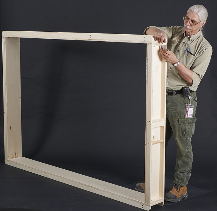
© Government of Canada, Canadian Conservation Institute. CCI 124851-0151
Figure 1. Plywood channels being assembled.
The front and back covers are made of triple-wall corrugated cardboard (triwall). This material is a strong, lightweight wood substitute that is inexpensive and can be easily recycled or reused. The cover edges are finished with reinforced kraft paper tape. Two cover fastening methods are described here. Option 1 is a closure with wood screws; option 2 is a closure with machine screws that engage with threaded inserts permanently installed in the channel rails (Figure 9).
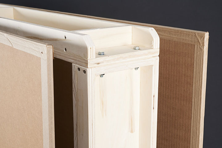
© Government of Canada, Canadian Conservation Institute. CCI 124851-0146
Figure 2. Corner detail showing assembly hardware and triwall cardboard covers with reinforced kraft paper tape on the edges.
Channel crates for paintings
The channel crate and a handling-transportation-storage (HTS) frame offer a flexible solution for shipping paintings of various sizes (Figure 3a). An HTS frame can contain one painting or several. Two or more HTS frames can also be joined together face to face using draw latches or other suitable hardware.
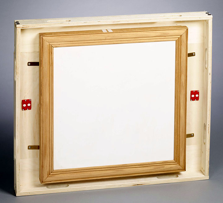
Figure 3a. Painting attached inside an HTS frame.
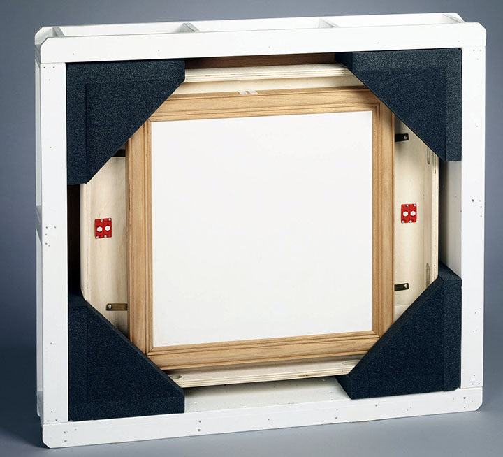
Figure 3b. Cushioned HTS frame inside a channel crate.
© Government of Canada, Canadian Conservation Institute. CCI 124851-0149
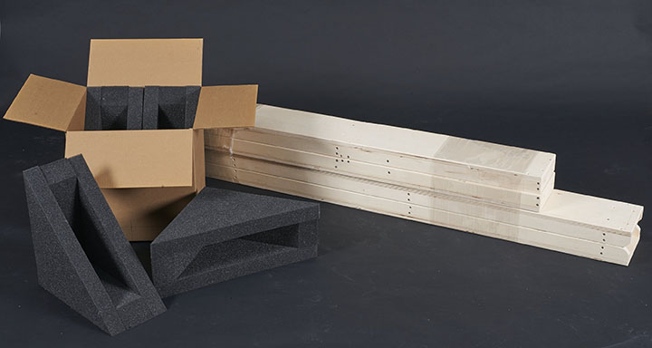
Figure 4. The disassembled channel crate components: foam pads in corrugated carton on the left; channel sections on the right.
Thermal insulation
If additional thermal insulating ability is required, rigid polystyrene insulating panels can be added externally, inside the channel’s recesses, and internally, underneath the two cover panels.
Shipping and return for reuse
After the outbound shipment, the plywood channels and protective cushions can be returned to the sender for reuse in a compact form that can be shipped at low cost by common carriers. The corner pads can be packed neatly inside a fitted corrugated box that is flat-packed inside the channel crate on the outbound shipment.
The condition of channel crate parts returned to date suggests that the channel sections can provide long service life if they are stored and shipped with reasonable care. Wrapping the channels in polyethylene or shrink wrap or packing them in light cardboard can help protect them during their return shipment.
Two additional features can also help extend the service life of the crate. The first is replaceable skids to protect the base channel from wear and damage (consult Channel parts and skids). The second is the application of paint or a clear coat finish to help protect the channel sections from moisture.
The material and fabrication costs of a high-quality plywood crate plus the cushioning required for a medium-sized painting can approach $1,000Endnote 2. The cost of a channel crate and cushioning for the same painting is approximately $450, plus triwall cover material at a cost of $20 per sheet. This can reduce packaging costs by as much as 50%. For a scenario where the sender supplies the crate on a loan basis and the recipient covers the cost of the cover panels plus return shipment of the major crate parts back to the sender, the savings can approach 80% or more.
Constructing a channel crate
The crate can be constructed with typical workshop tools, equipment and supplies. All of the wood and corrugated cardboard part sizes are derived from the required interior dimensions (consult Tables 1 and 4).
Note: CCI has created a channel crate design tool as an Excel workbook. The tool calculates the dimensions of each plywood and corrugated cardboard part using the same equations shown in the sections on Channel parts and skids and Cover panels and fasteners. It also calculates external crate dimensions, crate weight, construction and cover fastener spacing, vertical and horizontal rib count and spacing as well as the total quantity and cost of materials and hardware.
© Government of Canada, Canadian Conservation Institute. CCI 131500-0005
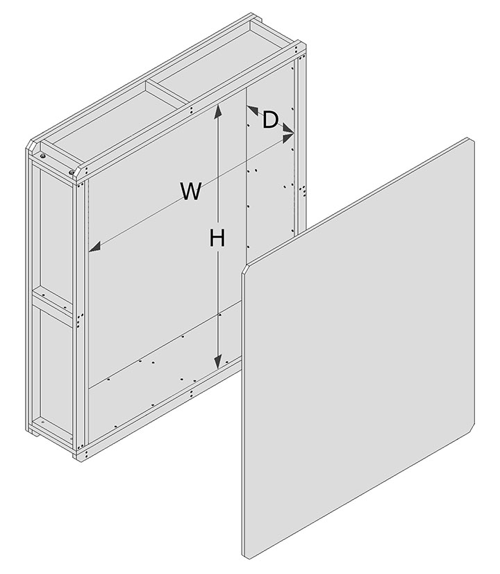
Figure 5. A crate with the front cover removed. Interior height (H), width (W) and depth (D) indicated.
Channel parts and skids
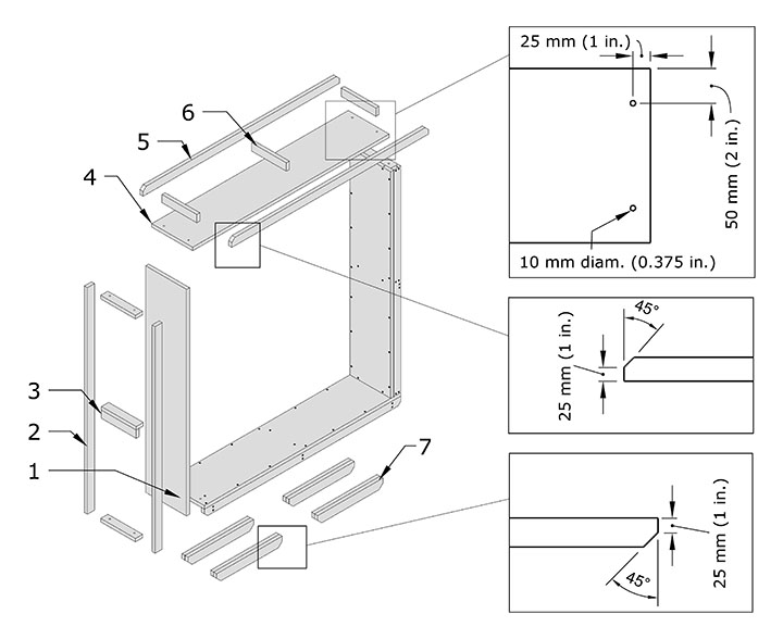
The preferred channel material is high-quality industrial poplar plywood, good on two sides, 19 mm (3/4 in.) thick, but other types of plywood may also be used. The plywood part dimensions are derived from the interior crate dimensions using the equations in Table 1. Drill two holes on both ends of the horizontal panels (part 4 in Figure 6). The holes should be 10 mm (0.375 in.) in diameter.
Skids can be added as an option. Each skid is made of two plywood parts (part 7 in Figure 6) laminated together. The ends can be bevelled, as shown, or rounded.
© Government of Canada, Canadian Conservation Institute. CCI 131500-0007
Figure 6. Plywood parts for channels and skids.
Description of Figure 6
The plywood parts are:
- Left vertical panel
- Vertical rail to stiffen vertical panel
- Handle made from two reinforcing ribs
- Horizontal panel with two holes drilled into both ends; each hole is 10 mm (0.375 in.) in diameter and located 25 mm (1 in.) from the end of the panel and 50 mm (2 in.) from the side
- Horizontal rail to stiffen horizontal panel; the top edge of the reinforcing rail should be bevelled at a 45° angle, leaving the bevelled edge about 25 mm (1 in.) high
- Reinforcing rib, to use when channel sections exceed 500 mm (20 in.)
- Skid made of two plywood parts laminated together; the lower edge of the skid should be bevelled at a 45° angle, leaving the bevelled edge about 25 mm (1 in.) high
| Part | Description | Quantity | Dimensions (mm) | Dimensions (in.) |
|---|---|---|---|---|
| 1 | Vertical panel | 2 | (H) × (D) | (H) × (D) |
| 2 | Vertical rail | 4 | (H) × (44) | (H) × (1 3/4) |
| 3 | Handle | As required | (D − 38) × (44) | (D − 1 1/2) × (1 3/4) |
| 4 | Horizontal panel | 2 | (W + 127) × (D) | (W + 5) × (D) |
| 5 | Horizontal rail | 4 | (W + 127) × (44) | (W + 5) × (1 3/4) |
| 6 | Rib | As required | (D − 38) × (44) | (D − 1 1/2) × (1 3/4) |
| 7 | Skid | As required | 406 × 50 | 16 × 2 |
Channel construction
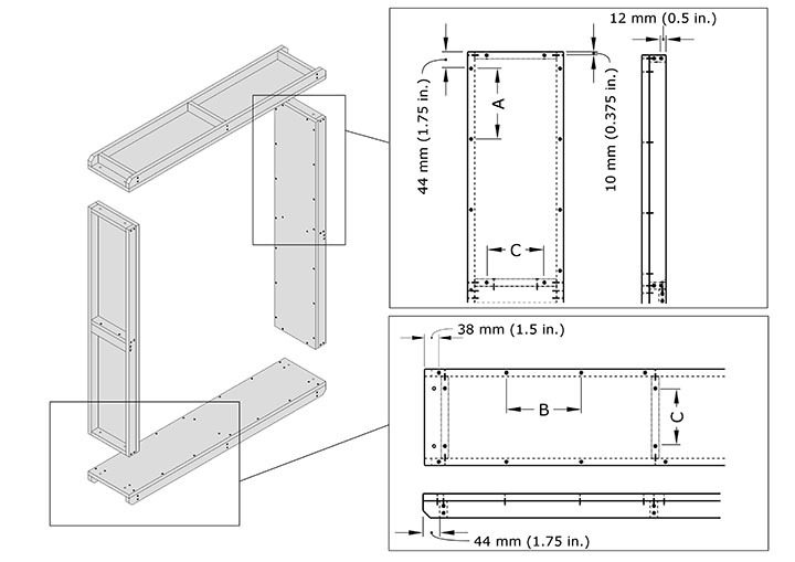
Use wood glue and 4 mm × 40 mm (#8Endnote 3 × 1 1/2) wood screws to construct the channel sections. Spacing between screws A, B and C in Figure 7 is approximately 178 mm (7 in.). Add reinforcing ribs (part 6 in Figure 6) when unreinforced channel sections exceed 500 mm (20 in.) in length. Construct handles with two ribs. Accurately align the channel section corners, clamp them together temporarily and use the horizontal channel holes as guides to drill the vertical channel end holes.
© Government of Canada, Canadian Conservation Institute. CCI 131500-0009
Figure 7. Right and left channels (top, side and bottom view).
Description of Figure 7
Diagram showing the construction of the channel sections numbered in Figure 6 with reinforcing ribs. On the vertical panel, assembly screw spacing (shown as A and C) is about 178 mm (7 in.) to secure the stiffening rails to the panel. The last screw is about 44 mm (1.75 in.) from the panel edge. The screw spacing for one rib is shown (C). Rib ends are secured with screws through the rails and spaced about 12 mm (0.5 in.) apart. The ends of the ribs are flush with the panel end.
On the horizontal panel, assembly screw spacing (shown as B and C) is about 178 mm (7 in.) to secure the stiffening rails to the panel. The last screw is about 44 mm (1.75 in.) from the panel edge. The screw spacing for one rib is shown (C). Rib ends are secured with screws through the rails and spaced about 12 mm (0.5 in.) apart. The ends of the ribs are located 44 mm (1.75 in.) from the panel ends to allow space for assembly nuts, bolts and washers.
| Part | Description | Metric | Imperial |
|---|---|---|---|
| 8 | Wood screws | 4 mm × 40 mm | #8 × 1 1/2 in. |
Channel assembly and skids
Assemble channel sections with M8 (5/16 in.) nuts, bolts and washers. Install skids, if used, using 50 mm (2 in.) screws.
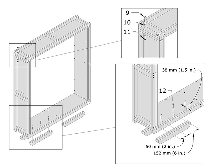
© Government of Canada, Canadian Conservation Institute. CCI 131500-0011
Figure 8. Channel assembly, hardware and skids.
Description of Figure 8
Diagram showing how to assemble the channel and skids with hardware.
Part 9: assembly bolt M8, 1.25 mm pitch, 50 mm long (5/16 in., 24 threads per inch, 2 in. long)
Part 10: assembly washer M8 (5/16 in.)
Part 11: assembly nut M8, 1.25 mm pitch (5/16 in., 24 threads per inch)
Part 12: wood screws to attach optional skids, 4 mm by 50 mm long (number 8 by 2 in. long)
Assembly hardware to fasten horizontal and vertical panels consists of M8-1.25 × 50 mm (5/16-24 in. × 2 in.) bolts and M8 (5/16 in.) washers. The bolt passes through the horizontal channel, then through the vertical channel, followed by a second M8 (5/16 in.) washer and one M8 by 1.25 mm pitch (5/16 24 thread per inch) nut.
A detail of the optional skids shows that the skids are attached to the horizontal base channel using 50 mm (2 in.) wood screws, adjacent to the stiffening rail and placed inside the channel recess. The first screw is spaced 50 mm (2 in.) from the inner vertical panel surface and driven from the inside panel surface. The second and third screws follow in line and are spaced 152 mm (6 in.) apart.
| Part | Quantity | Description | Metric | Imperial |
|---|---|---|---|---|
| 9 | 8 | Assembly bolts | M8-1.25 × 50 mm | 5/16-24 in. × 2 in. |
| 10 | 16 | Assembly washers | M8 | 5/16 in. |
| 11 | 8 | Assembly nuts | M8-1.25 mm | 5/16-24 in. |
| 12 | Skids × 3 | Wood screws (for skids) | 4 mm × 50 mm | #8 × 2 in. |
Cover panels and fasteners
Two cover fastening options are shown below. The cover fastener spacing for F and G in Figure 9 is approximately 229 mm (9 in.) along the rail centreline. If insulation is added or if a different cover panel thickness is used, select screw length accordingly. Cut a 6 mm (0.25 in.) strip off the bottom of the triwall covers if skids are not used to prevent direct contact between the cardboard edge and the ground surface. After the covers are cut to size, finish the edges with reinforced kraft paper tape (Figure 2).
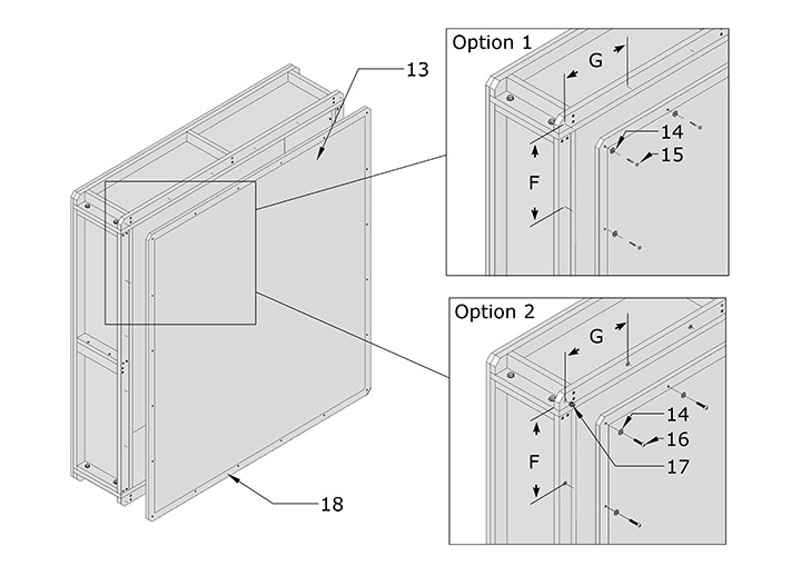
© Government of Canada, Canadian Conservation Institute. CCI 131500-0013
Figure 9. Two options for a cover attachment are shown in the detail drawings. Option 1: insert nuts and machine screws. Option 2: use washer head wood screws.
Description of Figure 9
F and G denote cover fastener spacing at about 229 mm (9 in.), which is the same for both options.
Part 13: triwall corrugated cover panel
Part 14: cover washer M6 (1/4 in.)
Part 15: wood screw for cover attachment M4 by 40 mm long (number 8 by 1 1/2 in. long)
Part 16: machine screw for cover attachment M6, 1 mm pitch by 13 mm long (1/4 in. 20 threads per inch by 1 1/4 in. long)
Part 17: insert nut installed in reinforcing rail M6, 1 mm pitch by 13 mm long (1/4 in. 20 threads per inch 1/2 in. long)
Part 18: reinforced kraft tape finish applied to the edge of the triwall cover tape is 76 mm (3 in.) wide and bonded to the edge and the two adjacent flat faces
| Part | Quantity | Description | Metric | Imperial |
|---|---|---|---|---|
| 13 | 2 | Cover | (H + 127 mm) × (W + 127 mm) | (H + 5 in.) × (W + 5 in.) |
| 14 | As required | Washers | M6 | 1/4 in. |
| 15 | As required | Washer head screw | M4 × 40 mm | #8 × 1 1/2 in. |
| 16 | As required | Machine screws | M6-1 × 30 mm | 1/4-20 in. × 1 1/4 in. |
| 17 | As required | Insert nuts | M6-1 × 13 mm | 1/4-20 in. × 1/2 in. |
| 18 | As required | Reinforced kraft paper tape | 76 mm | 3 in. |
Final comments
The channel crate is a lightweight and durable crating option. However, as a light duty container, it may not be an adequate substitute for a more durable wooden crate in some distribution networks. When matched to the object weight and distribution network, it can offer a good assurance of safe shipment for some items while making good use of resources and helping to reduce packaging costs.
Bibliography
Snutch, D., and P. Marcon. Making Triwall Containers. CCI Notes 1/4. Ottawa, ON: Canadian Conservation Institute, 1997.
By Paul Marcon
Revised in 2024
Originally published in 2020
© Government of Canada, Canadian Conservation Institute, 2024
Cat. No.: NM95-57/20-1-2020E-PDF
ISSN 1928-1455
ISBN 978-0-660-34550-5